10
– English
English
e)
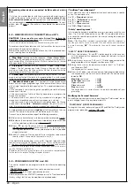
- position one end of the rack above the gearmotor pinion, taking
care to align the first fixing bracket with the centre of the pinion (
fig. 14
).
f)
- using a spirit level, level the first section of the rack in the pinion
area and temporarily secure to the gate leaf by means of adhesive
tape.
Then repeat the same operations on the next section and so on
through the entire length of the rack, taking care to position each
section horizontally and perfectly aligned with the end placed on the
pinion.
g)
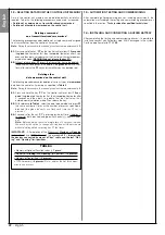
- Tighten the fixing brackets fully down on the gate leaf as follows
(
fig. 15
):
first secure the two brackets in the vicinity of the gear-
motor by means of screws and washers (with the gate com-
pletely closed). Then move the gate to bring the next bracket in
alignment with the pinion and secure it to the leaf.
Repeat the same operation for the next bracket and so on until all
brackets on the rack are secured.
Note
– The screws required to fix the rack on the gate leaf are not
included in the pack as their type depends on the material and thick-
ness of the leaf on which they are inserted.
h)
- before securing the last section of the rack, completely open the
gate and check that the bracket on the end is aligned with the centre
of the pinion. If this is not so, move the bracket to this position and, if
necessary, use a hacksaw to cut off the excess section of the rack,
leaving a free section of approx. 5 cm.
IMPORTANT
-
the rack must
not protrude from the gate leaf.
Caution
– At the end of this work, check that the rack is per-
fectly level; the slots on the brackets enable corrections of small
differences in alignment during fixture.
08.
Then secure the gearmotor onto the foundation plate, tightening the
two locknuts fully down:
the pinion must be perfectly aligned with the
rack; if necessary slide the gearmotor forwards or backwards to
adjust.
09.
Release the gearmotor by means of the special release key (see
chapter “
Manually releasing or locking the gearmotor
” in the
“Operation manual”)
and move the gate leaf to mid-travel
.
10.
Make a number of complete manual gate
opening
and
closing
manoeuvres to enable self-adjustment of the mechanical limit
switches.
Important
– During this manoeuvre, ensure that the rack
slides in alignment with the pinion.
11.
Then
move the gate leaf to mid-trave
l and lock the gearmotor
by means of the special key (see chapter “
Manually releasing or
locking the gearmotor
” in the “Operation manual”).
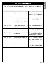
Note
– The 4 stud bolts supplied in the pack must be used exclusively to
adjust the gearmotor height, when deciding to assembly the rack before
the gearmotor (
fig. 16
).
15
12
13
16
14
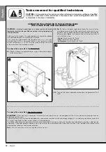
80 mm
Right-hand positioning of the gearmotor
“Closing”
position
C
80 mm
Left-hand positioning of the gearmotor
“Closing”
position
C


