background image

11

1.  Measure from range top to desired hood bottom location and 

mark line A.  (24” minimum from range top) .

2.  Plum and mark center line.
3.  Mark hood height line B. (11-1/16” from line A)
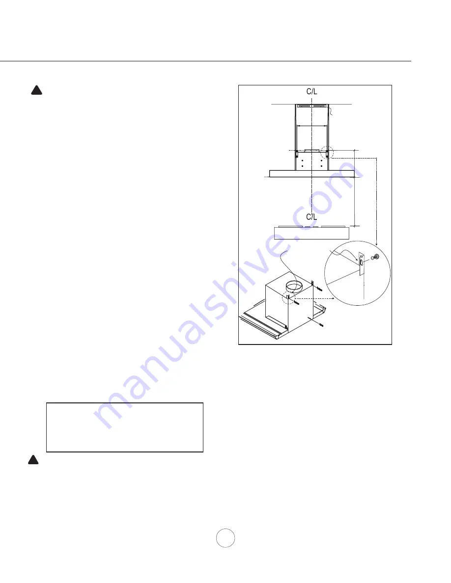
4.  Mark mounting spread from C/L. (12-5/8” on line B) 
5.  Fasten (2) #6 x 1-1/2” screws into studs on line B but do not 

tighten all the way.  

Note: Wood blocking may need to be 

added behind the drywall if no studs are present.  Wall 

anchors may also be used but check local codes for 

compliance. Failure to use suitable wall anchors to hold 

the weight of the hood could result in personal injury or 

damage to the cooking surface or counter.

6.   Remove (2) screws securing electrical junction box to hood 

body. Remove junction box. 

7.  Remove the (2) filters. Hang hood onto the mounting screws 

and hand tighten each screw. (FIG. A #1) Secure third #6 x 

1-1/2” screw with washer through inside of hood into wall for 

extra support. (FIG. A #2)

8.  Center and attach duct cover mounting bracket to wall just 

below the ceiling or soffit using (2) #6 x 1” screws. (FIG. A #3)

9. Install duct work and seal with aluminum duct tape*. Re-install 

junction box with cable lock and install the electrical. Power up 

hood to verify all functions and check for leaks around duct tape

10. Place telescopic duct covers onto hood and extend inner (top) 

duct cover upwards and secure to duct cover bracket using (2) 

4 x 8mm screws. Re-install filters.

   * If using hood in recirculating mode you must secure the air 

diverter plate onto wall before installing duct work and duct 

covers. Refer to page 14 for more details.

11 

1/16

Brackets are 
pre-installed

24” Min.

A

B

3

1

2

Duct Cover Bracket

12 

5/8

CAUTION: At least two installers are

required due to the weight and size of the

hood.

!

WARNING:  Electrical  wiring  must  be  done  by  a  qualified  person(s)  in

accordance with all applicable codes and standards. This range hood must be

properly grounded. Turn off electrical power at service entrance before wiring.

!

Cable Lock

A cable locking connector (not supplied) might 

be required by local codes.  Check with local 

requirements and codes, purchase and install 

appropriate connector if necessary.

Installation – 

Mounting the Hood MH008

FIG. A

Summary of Contents for MH00630BS

Page 1: ...2018 SEP JUL18 0101 MH00630BS MH00636BS MODEL MH00830BS MH00836BS ...

Page 2: ......

Page 3: ...ood Specifications RH006 8 Hood Specifications RH008 9 Mounting the Hood RH006 10 Mounting the Hood RH008 11 Ductless Recirculating 12 FEATURES CONTROLS Electronic Controls 13 MAINTENANCE Hood and Filter Cleaning 14 CFM SELECT 15 WIRING DIAGRAMS 16 TROUBLESHOOTING 17 LIST OF PARTS AND ACCESSORIES 18 WARRANTY 19 Table of Contents ...

Page 4: ... of and amount of food being prepared WARNING TO REDUCE THE RISK OF INJURY TO PERSONS IN THE EVENT OF A RANGE TOP FIRE OBSERVE THE FOLLOWING a SMOTHER FLAMES with a close fitting lid cookie sheet or metal tray then turn off the burner BE CAREFUL TO PREVENT BURNS If the flames do not go out immediately EVACUATE AND CALL THE FIRE DEPARTMENT b NEVER PICK UP A FLAMING PAN You may be burned c DO NOT US...

Page 5: ...or CSA standards C22 1 94 Canadian Electrical Code Part 1 and C22 2 No 0 M91 latest edition and all local codes and ordinances If codes permit and a separate ground wire is used it is recommended that a qualified electrician determine that the ground path is adequate Do not ground to a gas pipe Check with a qualified electrician if you are not sure the range hood is properly grounded Do not have a...

Page 6: ...RDWARE PACKAGE CONTENTS PARTS SUPPLIED 1 Hood with internal blower 1 Duct cover wall bracket 1 Duct cover assembly top and bottom 1 Hardware package 1 6 round backdraft damper pre installed 1 5W LED Light Strip 2 Baffle Filters MH00630BS MH00636BS 4 6 x 1 1 2 2 6 x 1 2 4 x 8mm 3 Wire Nuts MH00830BS MH00836BS 3 6 x 1 1 2 2 6 x 1 2 4 x 8mm 3 Wire Nuts List of Materials ...

Page 7: ...olumn 2 Subtotal column 1 Total ductwork Maximum Duct Length For satisfactory air movement the total duct length should not exceed 100 equivalent feet 6 roundto 3 1 4 x 10 rect transition 1 Ft x Ft 6 roundto 3 1 4 x 10 rect transition 900 elbow 16 Ft x Ft 7 roundto 3 1 4 x 10 rect transition 8 Ft x Ft 7 roundto 3 1 4 x 10 rect transition 900 elbow 23 Ft x Ft elbow elbow 7 to 6 or 8 to 7 Round tape...

Page 8: ...mended hood mounting height above range Always check your local codes for any differences Duct cover extension kit available for ceiling heights up to 12 feet Turn to page 18 for part number and ordering information DAMAGE SHIPMENT INSTALLATION Please fully inspect unit for damage before installation If the unit is damaged in shipment return the unit to the store in which it was bought for repair ...

Page 9: ...e outside unless using the recirculating option Use single wall rigid metal ductwork only Fasten all connections with sheet metal screws and tape all joints w certified Silver Tape or Duct Tape Some Ducting Options Installation Ducting Options side wall cap w gravity damper Soffit or crawl space Roof Pitch w Flashing Cap ductless recirculating side wall cap w gravity damper ...

Page 10: ...d Specification MH006 1 1 1 8 13 16 3 7 16 29 15 16 8 3 4 6 3 4 12 19 3 4 35 7 8 Standard Duct Cover Min ducted 27 1 2 Min recirc 32 Max ducted 42 1 2 RHEX001S Extension Min ducted 46 1 2 Min recirc 50 1 2 Max ducted 80 ...

Page 11: ... Hood Specification MH008 29 15 16 35 7 16 14 1 8 2 13 16 20 1 16 STANDARD min ducted 26 min recirc 31 max 49 RHEX008S EXTENSION min ducted 41 min recirc 45 1 2 max 78 1 2 11 10 9 16 5 1 5 1 6 CL 1 3 16 3 9 16 4 1 2 ...

Page 12: ...r and attach duct cover bracket to wall below ceiling or soffit using 2 6x1 screws 8 Install electrical 9 Install duct work and duct tape 10 Power up hood and check for leaks around duct tape 11 Place telescopic duct covers onto hood and extend inner top duct cover upwards and secure to duct cover bracket using 2 4 x 8mm screws If using hood in recirculating mode you must secure air diverter plate...

Page 13: ... or soffit using 2 6 x 1 screws FIG A 3 9 Install duct work and seal with aluminum duct tape Re install junction box with cable lock and install the electrical Power up hood to verify all functions and check for leaks around duct tape 10 Place telescopic duct covers onto hood and extend inner top duct cover upwards and secure to duct cover bracket using 2 4 x 8mm screws Re install filters If using...

Page 14: ...al filters help to purify fumes exhausted from cooking for re circulation RECIRCULATING KIT REQUIRED IF NO DUCTING IS USED Kit includes charcoal filters charcoal filter brackets and air diverter plate Hood Models Part No Filters Brackets in pkg MH006 RHRK006BS 2 MH008 RHRK008BS 2 1 Purchase recirculating kit per the part number above 2 Secure air diverter plate to wall below duct cover bracket FIG...

Page 15: ...local codes and regulations To verify the maximum fan CFM With hood off press and hold the power button for five seconds If all three fan speed indicators illuminate default maximum CFM If two speed level indicators illuminate 390 maximum CFM If only one speed level indicator illuminates 290 maximum CFM Lights are two levels low and high From off press once for low press again for high press again...

Page 16: ...non abrasive stainless steel polish cleaners to polish and buff out the stainless luster and grain Always scrub lightly with clean cotton cloth or micro fiber cloth and buff in the direction of the stainless steel grain Baffle Filters The baffle filters installed by the factory are intended to filter out residue and grease from cooking They need not be replaced on a regular basis but are required ...

Page 17: ...clearly visible location NOTE After re positioning the jumper and powering on the hood the CFM cannot be changed again To verify if your installer enabled CFM Select With hood off press and hold the power button for five seconds If 3 LEDs illuminate defualt max CFM if 2 LEDs illuminate max 390 CFM and if 1 LEDs illuminate max 290 CFM When CFM Select is enabled the number of blower speeds will be r...

Page 18: ...16 Wiring Diagrams MH00630BS MH00636BS GRAY MH00830BS MH00836BS ...

Page 19: ...own 5 Damaged capacitor 5 Change the capacitor 6 The switch board or control board is defective 6 Change defective part The unit is vibrating 1 The blower is not secured in place 1 Tighten the blower in place 2 Damaged blower wheel 2 Replace the blower 3 The hood is not secured in place 3 Check the installation of the hood Only one or two fan speeds work 1 The installer may have adjusted the maxim...

Page 20: ...S RH008 Recirculating Kit RHRK008BS Replacement Charcoal Filters each Z0F C005 RH006 Extension Duct Cover RHEX001S RH008 Extension Duct Cover RHEX008S Replacement Parts Baffle Filter 50210034 Order replacement parts from us by calling 1 888 750 1698 List of Parts Accessories ...

Page 21: ...d professional installer to be eligible for warranty repairs or service Limitations of Warranty OUR OBLIGATION TO REPAIR OR REPLACE AT OUR OPTION SHALL BE YOUR SOLE AND EXCLUSIVE REMEDY UNDER THIS WARRANTY WE SHALL NOT BE LIABLE FOR INCIDENTAL CONSEQUENTIAL OR SPECIAL DAMAGES ARISING OUT OF OR IN CONNECTION WITH THE USE OR PERFORMANCE OF THE PRODUCTS THE EXPRESS WARRANTIES IN THE PRECEDING SECTION...

Reviews: