


13
CFM SELECTOR
Some local codes limit the maximum amount of CFM a range hood can move. CFM Selector allows you to control
the maximum blower CFM without the need for expensive make up air kits. CFM Selector enables the installer
to easily set the maximum blower speed to one of two most commonly specified CFM levels; 590 or 390 CFM.
The usage of CFM Selector may not be necessary for your installation. Please check your local codes for CFM
restrictions.
By default the maximum blower CFM is set to 1200
To enable CFM Selector
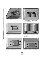
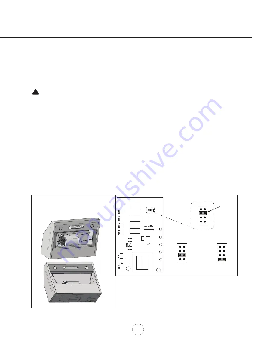
1. Before hood installation, gain access to PC board by following the steps shown in FIG. 1.
2. Change plastic jumper positioning as shown in FIG. 2 to set the desired maximum blower CFM.
3. Re-install PC board & continue with hood installation.
4. Remove the appropriate foil CFM sticker included with the hood literature and place inside the hood body below
the wiring diagram or in another clearly visible location.
NOTE:
After re-positioning the jumper and powering on the hood, the CFM cannot be changed again.
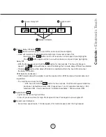
To verify if your installer enabled CFM Selector
With hood off, press and hold the power button for five seconds. If all three fan speed indicators illuminate = defualt
max. CFM, if speed 1 and 2 indicators illuminate = max. 590 CFM, and if only speed 1 level indicator illuminates =
max. 390 CFM.
When CFM Selector is enabled, the number of blower speeds will be reduced. 590 CFM = max. 2 speeds and 390
CFM = max. 1 speed.
There should also be a foil label located inside the hood body near the wiring diagram that indicates the blower CFM.
CFM Selector Conversion
CAUTION:
Hood must be disconnected from main power prior to performing the
conversion instructions listed below. Failure to do so could result in
personal injury or damage to the product.
!
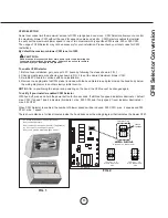
PC Board
1 3 5 7
2 4 6 8
Jumper 5-6 or 7-8
DEFAULT POSITION
Default Max. Blower CFM
Jumper 3-4
Max. Blower CFM
590
Jumper 1-2
Jumper Pins
Plastic
Jumper
1
3
5
7
2
4
6
8
1
3
5
7
2
4
6
8
1
3
5
7
2
4
6
8
Max. Blower CFM
390
FIG. 1
FIG. 2
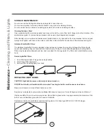
- Remove baffle filters.
- Remove both side spacer panels (if applicable)
by 2 screws for each spacer panel.
- Remove 4 screws attaching light panel.
- PC board located behind the light panel.


