background image

Troubleshooting

14

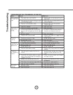
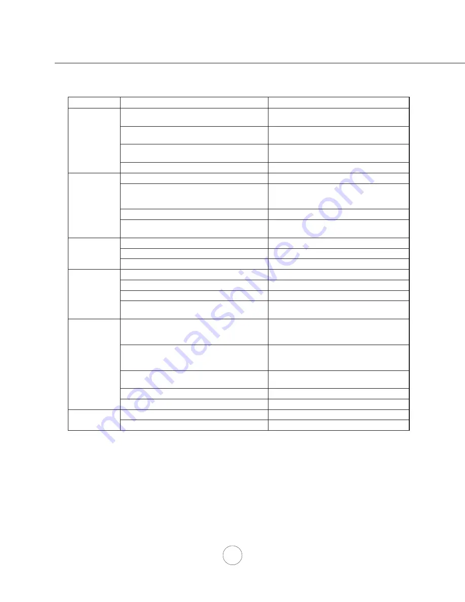
TROUBLESHOOTING PROCEDURES FOR MH702

Issue

Cause

What to do

After installation, 

the unit doesn’t 

work.

1.  The power source is not turned ON.

1.  Make sure the circuit breaker and the unit’s 

power is ON.

2.  The power line and the cable locking connector 

is not connecting properly.

2.  Check the power connection with the unit is 

connected properly.

3.  The wires on rotary switch are loose.

3.  Make sure the wires on the switch are 

connected properly.

4.  The switch is defective.

4.  Change the switch.

Light works, but 

blower is not 

turning.

1.  The blower is defective, possible seized.

1.  Change the blower.

2.  The thermally protected system detects if the 

blower is too hot to operate and shuts the blower 

down.

2.  The blower will function properly after the 

thermally protected system cool down.

3.  Damaged capacitor.

3.  Change the capacitor.

4.  The blower wire is not connected.

4.  Make sure the blower wire is plugged into the 

molex connector.

The unit is 

vibrating.

1.  The blower is not secure in place.

1.  Tighten the blower in place.

2.  Damaged blower wheel.

2.  Change the blower.

3.  The hood is not secured in place.

3.  Check the installation of the hood.

The blower is 

working, but the 

lights are not.

1.   The light bulb plug is disconnected.

1.   Check the light bulb plug connection.

2.  Defective halogen bulb.

2.  Change the halogen bulb.

3.  The light bulb is loose.

3.  Tighten the light bulb.

4.  The wires on the switch are loose.

4.  Make sure the wires on switch are connected 

properly.

The hood is 

not venting out 

properly.

1.  The hood might be hanging to high from the 

cook top.

1.  Adjust the distance between the cook top and 

the bottom of the hood within 24” and 36” 

range.

2.  The wind from the opened windows or opened 

doors in the surrounding area are affecting the 

ventilation of the hood.

2.  Close all the windows and doors to eliminate 

the outside wind flow.

3.  Blockage in the duct opening or duct work.

3.  Remove all the blocking from the duct work or 

duct opening.

4.  The direction of duct opening is against the wind. 4.  Adjust the duct opening direction.
5.  Using the wrong size of ducting.

5.  Change the ducting to correct size.

Metal filter is 

vibrating.

1.  Metal filter is loose.

1.  Change the metal filter.

2.  Spring clip is broken.

2.  Change the spring clip.

Summary of Contents for MH70230BS

Page 1: ...2018 SEP MH70230BS MH70236BS MH70248BS MODEL ...

Page 2: ......

Page 3: ...nce 6 Ducting Options 7 Specifications 8 Mounting the Range Hood Electrical 9 Horizontal Ducting Conversion 10 CONTROLS Electronic Touch 11 MAINTENANCE Cleaning Filters Lights 12 CFM SELECT CONVERSION 13 TROUBLESHOOTING 14 WIRING DIAGRAMS 15 LIST OF PARTS AND ACCESSORIES 16 WARRANTY 17 Table of Contents ...

Page 4: ... of and amount of food being prepared WARNING TO REDUCE THE RISK OF INJURY TO PERSONS IN THE EVENT OF A RANGE TOP FIRE OBSERVE THE FOLLOWING a SMOTHER FLAMES with a close fitting lid cookie sheet or metal tray then turn off the burner BE CAREFUL TO PREVENT BURNS If the flames do not go out immediately EVACUATE AND CALL THE FIRE DEPARTMENT b NEVER PICK UP A FLAMING PAN You may be burned c DO NOT US...

Page 5: ...ion is adequate and in conformance with National Electrical Code ANSI NFPA 70 latest edition or CSA standards C22 1 94 Canadian Electrical Code Part 1 and C22 2 No 0 M91 latest edition and all local codes and ordinances If codes permit and a separate ground wire is used it is recommended that a qualified electrician determine that the ground path is adequate Do not ground to a gas pipe Check with ...

Page 6: ...r Plate 1 Hardware package HARDWARE PACKAGE CONTENTS PARTS NOT SUPPLIED Ducting conduit and all installation tools Cable connector if required by local codes Duct Cover Accessory Backsplash Accessory Light Bulb Removal Suction Cup 1 6 x 1 4 6 x 1 1 2 4 6 x 2 4 M4 x 8 4 Wire Caps 3 3 16 x 3 8 4 Wood Board to hang hood W x D x H MH70230BS 27 x 1 2 x 4 MH70236BS 33 x 1 2 x 4 MH70248BS 45 x 1 2 x 4 ...

Page 7: ...10 Round roof cap 30 Ft x Ft Subtotal column 2 Subtotal column 1 Total ductwork Maximum Duct Length For satisfactory air movement the total duct length should not exceed 100 equivalent feet 6 roundto 3 1 4 x 10 rect transition 1 Ft x Ft 6 roundto 3 1 4 x 10 rect transition 900 elbow 16 Ft x Ft 7 roundto 3 1 4 x 10 rect transition 8 Ft x Ft 7 roundto 3 1 4 x 10 rect transition 900 elbow 23 Ft x Ft ...

Page 8: ...tant to install the hood at the proper mounting height Hoods mounted too low could result in heat damage and fire hazard while hoods mounted too high will be hard to reach and will lose its performance and efficiency If available also refer range manufacturer s height clearance requirements and recommended hood mounting height above range Vertical Ducting 10 round minimum Horizontal Ducting 10 rou...

Page 9: ...garages All exhaust must be ducted to the outside Use metal ductwork only Fasten all connections with sheet metal screws and tape all joints with certified Silver Tape or Duct Tape Some Ducting Options Installation Ducting Options Soffit or crawl space Roof Pitch w Flashing Cap Rear Ducting Side wall cap w gravity damper ...

Page 10: ... Dimensions 12 24 4 18 8 9 16 1 3 4 1 1 16 11 9 16 6 10 3 8 14 3 16 2 3 4 9 15 16 10 3 8 4 5 16 11 9 16 10 3 4 10 3 8 14 3 16 9 15 16 1 11 16 29 7 8 30 35 7 8 36 47 7 8 48 C L C L Back View Mounting Dimensions 16 7 8 16 1 8 13 5 8 1 11 16 3 5 16 21 1 4 27 3 8 36 35 1 4 48 5 5 16 ...

Page 11: ... 8 M4 wood screws 9 Further secure hood onto wall through lower body screw holes by 2 M4 wood screws 10 Install electrical 11 Install duct work and seal with certified aluminum duct tape 12 Power up hood and check for leaks around duct tape 13 Install baffle filters CAUTION At least two installers are required due to the weight and size of the hood ELECTRICAL WARNING All Electrical work must by pe...

Page 12: ...ion dual blower at back of hood Tuck dual blower plate under blower clips and secure blower to back of hood by 4 screws removed from step 2 5 Attach 10 round collar to back of hood body by 4 M4 x 8 screws 6 Attach top cover plate to top of hood body by 4 3 16 x 3 8 screws 2 Remove 4 screws attaching dual blower plate to top of interior body of hood Remove dual blower from hood body ...

Page 13: ... the hood off and cancel the delay off function CFM Selector Verification CFM Selector allows the installer to set the maximum fan CFM to align with local codes and regulations To verify the maximum fan CFM With hood off hold the button for five seconds If all three fan speed indicators illuminate default maximum CFM If speed level 1 and 2 indicators illuminate 590 maximum CFM If only speed level ...

Page 14: ...gh the filters should never need replacing they are required to be cleaned every 30 days or more often depending on cooking habits Filters may be placed in dishwasher at low heat or soaked in hot soapy water Dry filters and re install before using hood Removing Baffle Filters 1 Push filter toward back of range hood using handles 2 Pivot front of filter downward 3 Remove filter by pulling away from...

Page 15: ...on the hood the CFM cannot be changed again To verify if your installer enabled CFM Selector With hood off press and hold the power button for five seconds If all three fan speed indicators illuminate defualt max CFM if speed 1 and 2 indicators illuminate max 590 CFM and if only speed 1 level indicator illuminates max 390 CFM When CFM Selector is enabled the number of blower speeds will be reduced...

Page 16: ...lower in place 2 Damaged blower wheel 2 Change the blower 3 The hood is not secured in place 3 Check the installation of the hood The blower is working but the lights are not 1 The light bulb plug is disconnected 1 Check the light bulb plug connection 2 Defective halogen bulb 2 Change the halogen bulb 3 The light bulb is loose 3 Tighten the light bulb 4 The wires on the switch are loose 4 Make sur...

Page 17: ...Wiring Diagrams 15 MH70230BS MH70236BS MH70248BS ...

Page 18: ...10 50W each Z0B 0020 Optional Accessories Back Splash 30 AK0710 Back Splash 36 AK0716 Back Splash 48 AK0718 12 Duct Cover 30 AK0720 12 Duct Cover 36 AK0726 12 Duct Cover 48 AK0728 To order parts please call us at 1 888 750 1698 List of Parts and Accessories ...

Page 19: ...ied professional installer to be eligible for warranty repairs or service Limitations of Warranty OUR OBLIGATION TO REPAIR OR REPLACE AT OUR OPTION SHALL BE YOUR SOLE AND EXCLUSIVE REMEDY UNDER THIS WARRANTY WE SHALL NOT BE LIABLE FOR INCIDENTAL CONSEQUENTIAL OR SPECIAL DAMAGES ARISING OUT OF OR IN CONNECTION WITH THE USE OR PERFORMANCE OF THE PRODUCTS THE EXPRESS WARRANTIES IN THE PRECEDING SECTI...

Reviews: