65
ELECTRIC WIRE ROPE HOIST
XM SERIES
a
4. OPERATION AND MAINTENANCE INSTRUCTIONS
4.10 ADJUSTMENTS
4.10.1 ADJUSTMENT FO THE CONICAL HOIST
MOTOR BRAKE
This step must be performed with a still hoist and
without load.
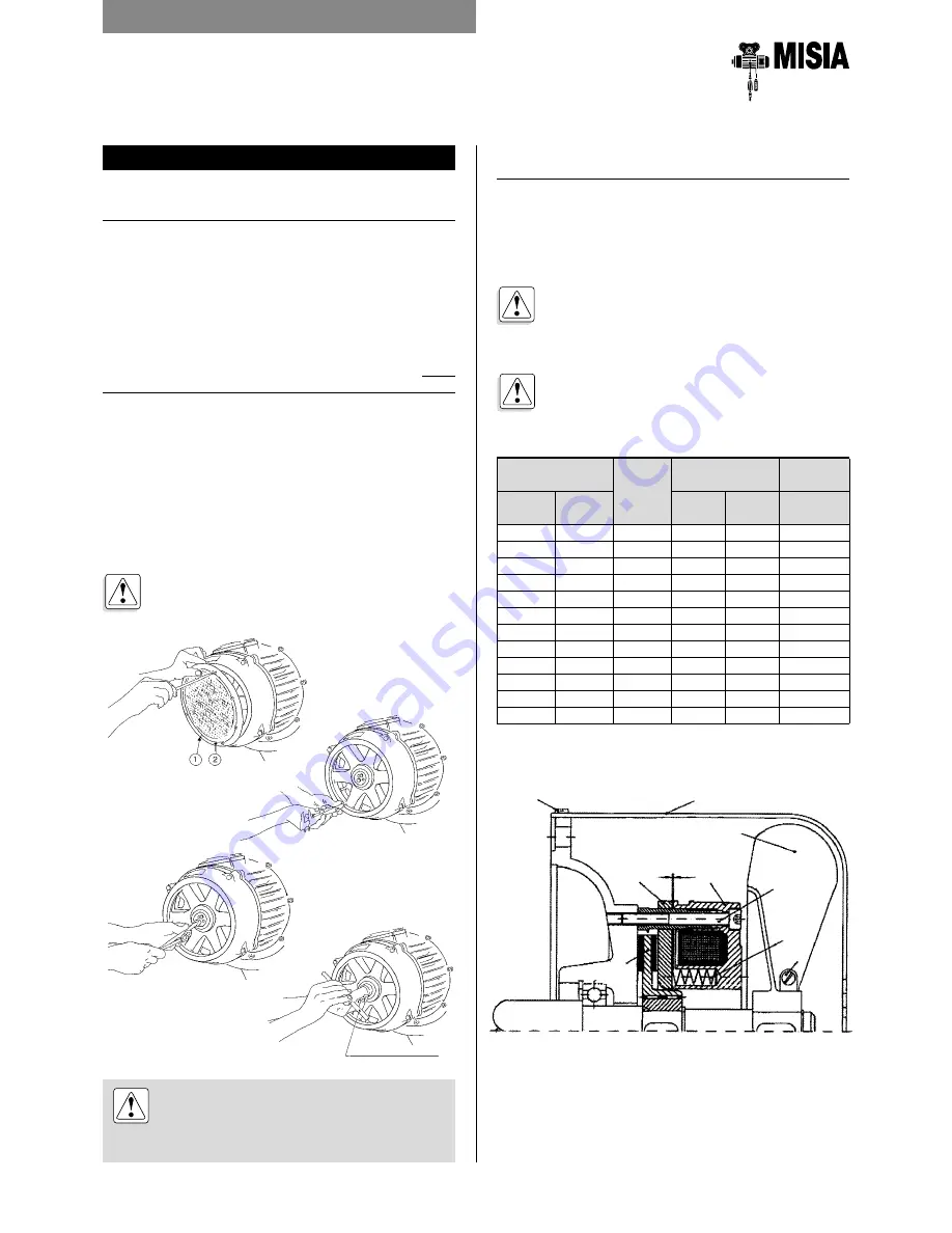
Loosen the screws pos. 1, remove the grid pos. 2,
(Fig. 19); with the brake applied, measure at any point
between the brake fan (Fig. 20) and the surface of the
bell. After this measurement, axially push the fan inside
the motor with the aid of a lever and make another
measurement, recording the difference (Fig. 20). If the
difference is greater than the rated values (0,8/1,2 mm)
proceed as follows:
• loosen the screw (Fig. 21) and then turn the adjusting
ring nut clockwise to take up any axial shifting greater
than the rated value, bearing in mind that one complete
turn of the ring nut corresponds to 2 mm (Fig. 22).
After this take up operation, repeat the measurement
with the brake released (Fig. 20), checking that the
axial shifting is within the rated value, then put back
the screws and the grid in their positions (Fig. 19).
If the measurement indicated is not reached
with the above operation, it is necessary to
replace the fan.
4.10.2 ADJUSTMENT OF BRAKE TYPE "M"
FOR CYLINDRICAL LIFTING MOTOR
- Check the magnetic gap (air gap) "a" and wear of the
brake as for table 16.
The air gap must be restored acting on the screws of
the body brake (position 5), screwing them clockwise
If the thickness of the disk brake is lower than
as shown in table16, it is necessary to replace
it by operating
as described in section 4.9.7.
NB: following the regulation of the magnetic
gap, the braking torque is restored.
ATTENTION! The brakes does not function
properly with an axial shifting over 2.5 mm.
The maximum permissible axial shifting of
the rotor during operation is of 2.5 mm.
Adjustment wrench
Fig. 19
Fig. 20
Fig. 21
Fig. 22
Table 16
Power kW
Type
brake
Air gap
Disk thick-
ness
4
poles
4/12
poles
mm
min.
mm
max
mm
min.
2,5
2,5/0,83
15
0,3
0,9
9,5
4
4/1,3
17
0,3
1,0
11,5
5
5/1,6
17
0,3
1,0
11,5
5,8
5,8/1,9
17
0,3
1,0
11,5
7
7/2,3
20
0,4
1,1
12,5
8
8/2,6
20
0,4
1,1
12,5
12
12/4
23
0,4
1,1
14,5
15
15/5
23
0,4
1,1
14,5
16
16/5,3
26
0,5
1,2
16,5
18
18/6
26
0,5
1,2
16,5
20
20/6,5
26
0,5
1,2
16,5
24
-
26
0,50
1,2
16,5
Summary of Contents for XM SERIES
Page 2: ......
Page 71: ...71 Manual for installation operation and maintenance of the wire rope hoists XM Series NOTE ...
Page 72: ...72 Manual for installation operation and maintenance of the wire rope hoists XM Series NOTE ...
Page 73: ...73 Manual for installation operation and maintenance of the wire rope hoists XM Series NOTE ...
Page 74: ...74 Manual for installation operation and maintenance of the wire rope hoists XM Series NOTE ...
Page 75: ......


