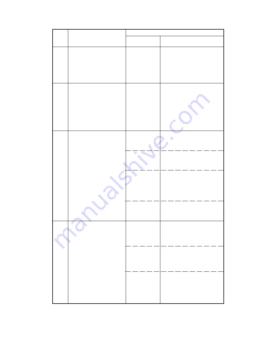
Code
Contents
Remarks
Causes
Check procedures/
corrective measures
2AR
3-5-7
Defective
main PCB.
Defective
main PCB.
Insufficient
exposure lamp
luminosity.
Defective
scanner
control PCB.
Incorrect
shading
position.
CCD PCB
output
problem.
Poor contact
of the drive
motor connec-
tor terminals.
Defective
drive motor
rotation
control circuit.
Defective
drive transmis-
sion system.
Replace the main PCB and
check for correct operation.
Replace the main PCB and
check for correct operation.
Replace the exposure lamp
or inverter PCB.
Replace the scanner control
PCB.
Adjust the position of the
contact glass (shading plate).
If the problem still occurs,
replace the scanner home
position switch.
Replace the ISU.
Reinsert the connector. Also
check for continuity within the
connector cable. If none, repair
or replace the cable.
Replace the drive motor.
Check if the rollers and gears
rotate smoothly. If not, grease
the bushings and gears.
Check for broken gears and
replace if any.
C042
Memory input interface
problem
Reading-in of an image
does not complete within
10 s of the start of image
transmission.
C043
DMA problem
DMA transmission of com-
pressed, decompressed,
rotated, relocated or
blanked-out image data
does not complete within
the specified period of
time.
C104
Optical system problem
After AGC, correct input is
not obtained at CCD.
C200
Drive motor problem
DM LOCK signal remains
high for 1 s or longer, 1 s
after the drive motor has
turned on.
3-5-6
Summary of Contents for PointSource Ai 3010
Page 1: ...3010 S M MCA SERVICE MANUAL Published in Apr 00 2AR70765 Revision 5 PointSource Ai 3010 R...
Page 2: ...Service Manual PointSource Ai 3010...
Page 13: ...3010 S M MCA THEORY AND CONSTRUCTION SECTION I I Theory and Construction Section...
Page 14: ...2AR CONTENTS 1 1 Specifications 1 1 1 Specifications 1 1 1...
Page 18: ...2AR CONTENTS 1 2 Handling Precautions 1 2 1 Drum 1 2 1 1 2 2 Developer and toner 1 2 1...
Page 61: ...3010 S M MCA ELECTRICAL SECTION II II Electrical Section...
Page 62: ...2AR CONTENTS 2 1 Electrical Parts Layout 2 1 1 Electrical parts layout 2 1 1 1 Copier 2 1 1...
Page 92: ...3010 S M MCA III Set Up and Adjustment Section III SET UP AND ADJUSTMENT SECTION...
Page 108: ...3 1 15 2AR This page has been left blank intentionally 2AR 5...
Page 136: ...3 2 11 2AR 1 This page is intentionally left blank...
Page 191: ...3 2 62 2AR 1 This page is intentionally left blank...
Page 196: ...3 2 61 2AR 1 This page is intentionally left blank...
Page 255: ...3 2 38 2AR 1 This page is intentionally left blank...
Page 384: ...2AR 1 3 6 15 This page is intentionally left blank...
Page 398: ...3 6 27 2AR 1 3 Main PCB CN9 CN5 CN2 CN3 CN4 IC11 IC12 CN1 CN8 CN10 CN11 CN6 CN7...
Page 431: ...2AR General connection diagram 3 7 43 General wiring diagram 3 7 44 2AR 1...


