15
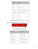
5 BKLT_GND/Brightness_GND Ground (shared)
6 BKLT_GND/Brightness_GND Ground (shared)
7 Brightness_Up
Panel brightness increase
8 Brightness_Down
Panel brightness decrease
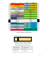
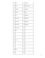
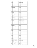
Table 5:
8-pin FPD power connector pin-out
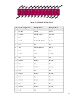
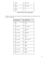
Figure 6: Front panel audio header
Pin Signal name
Description
1 MIC
Front panel microphone input signal (biased when supporting stereo microphone)
2 AUD_GND
Ground used by analog audio circuits
3 MIC_BIAS
Microphone power / additional MIC input for stereo microphone support
4 PRESENCE#
Active low signal that signals BIOS that an Intel® HD Audio dongle is connected to the
analog header. PRESENCE# = 0 when an Intel® HD Audio dongle is connected.
5 FP_OUT_R
Right channel audio signal to front panel (headphone drive capable)
6 AUD_GND
Ground used by analog audio circuits
7 RESERVED
Reserved
8 KEY
No pin
9 FP_OUT_L
Left channel audio signal to front panel (headphone drive capable)
10 AUD_GND
Ground used by analog audio circuits
Table 6:
Passive AC’97 front panel audio header pinout
Summary of Contents for P150-10AI
Page 1: ...MiTAC Panel PC System P150 10AI Product Guidev1 2 ...
Page 2: ...2 Front View Rear View ...
Page 3: ...3 Bottom View Mechanical Dimension P150 10AI dimension 360 4mm x 283 4mm x 66 7mm ...
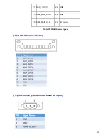
Page 31: ...31 2pin terminal block PIN Signal name 1 ground 2 Powerswitch ...
Page 32: ...32 MITAC Embedded System P150 10AI BIOS Specifiction ...
Page 66: ...66 Help Change the Printer Port mode Comment SKU S did not have Parallel port menu ...
Page 86: ...86 Press Enter when selected to go into the associated Sub Menu ...


