20
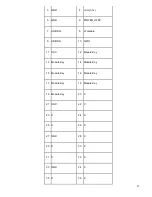
5
GROUND
Ground
6
POWER_SWITCH#
[In] Power switch
7
RESET_SWITCH#
[In] Reset switch
8
GROUND
Ground
9
+5V_DC
Power
10
KEY
No pin
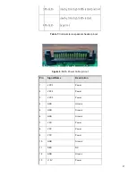
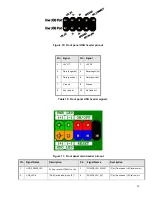
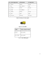
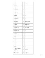
Table 11: Front panel main header signals
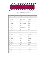
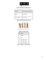
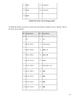
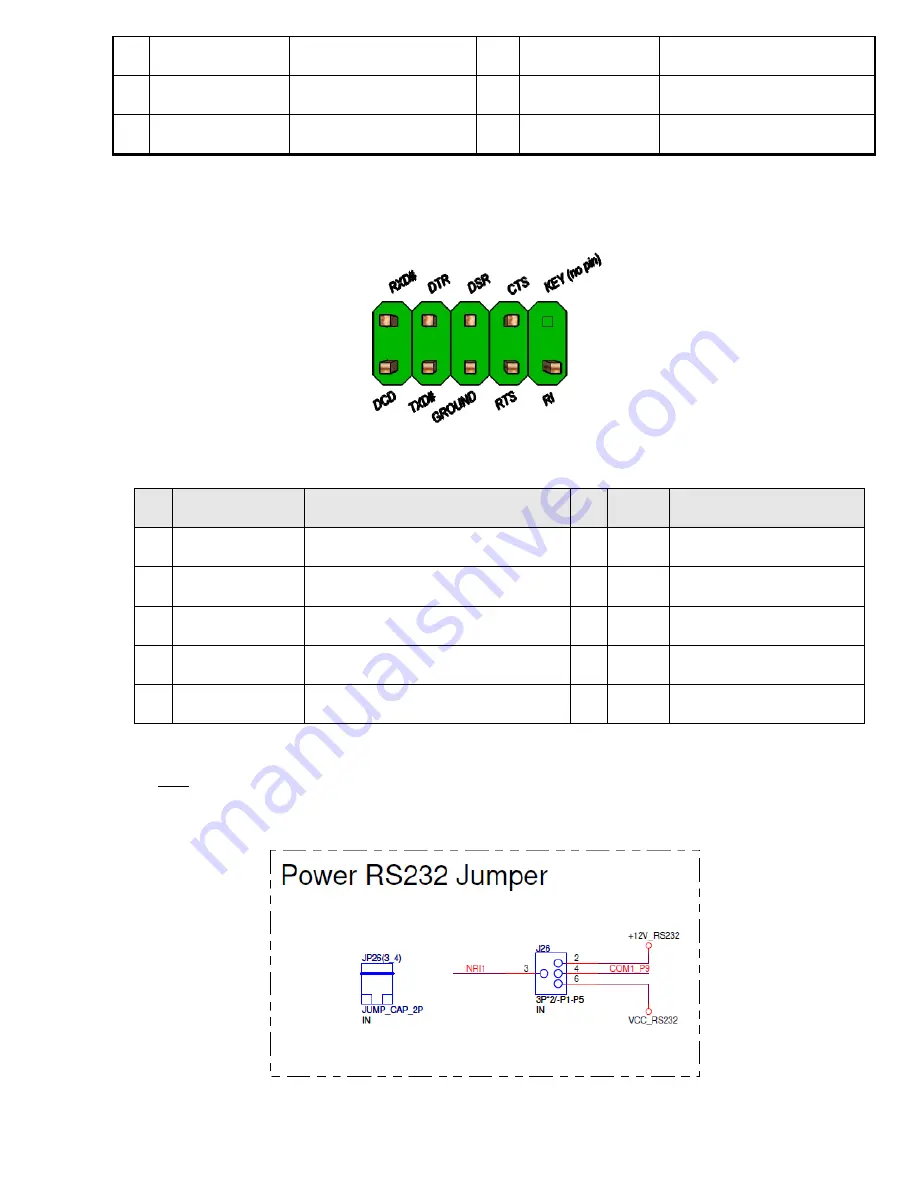
Figure 12: serial port pin out
Pin
Signal
Pin
Signal
1
COM3_P1_40mils
DCD (Data Carrier Detect)
2
NRX3
RXD# (Receive Data)
3
NTX3
TXD# (Transmit Data)
4
NDTR3
DTR (Data Terminal Ready)
5
GND
Ground
6
NDSR3
DSR (Data Set Ready)
7
NRTS3
RTS (Request To Send)
8
NCTS3
CTS (Clear To Send)
9
COM3_P9_40mils
RI (Ring Indicator)
10 Key
Key (no pin)
Table 12: Power RS232 Serial port header signals
Note: The serial port header must be placed within a keep-out-zone no smaller than 1 inch (half-inch to
the left and half-inch to the right of the header) so as to support commonly available dongles.
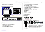
Summary of Contents for P150-10AI
Page 1: ...MiTAC Panel PC System P150 10AI Product Guidev1 2 ...
Page 2: ...2 Front View Rear View ...
Page 3: ...3 Bottom View Mechanical Dimension P150 10AI dimension 360 4mm x 283 4mm x 66 7mm ...
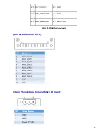
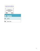
Page 31: ...31 2pin terminal block PIN Signal name 1 ground 2 Powerswitch ...
Page 32: ...32 MITAC Embedded System P150 10AI BIOS Specifiction ...
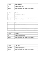
Page 66: ...66 Help Change the Printer Port mode Comment SKU S did not have Parallel port menu ...
Page 86: ...86 Press Enter when selected to go into the associated Sub Menu ...


