22
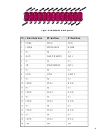
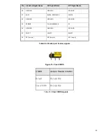
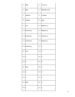
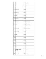
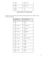
Figure 14: Parallel port header pin-out
Pin Standard Signal Name
ECP Signal Name
EPP Signal Name
1
STROBE#
STROBE#
WRITE#
2
AUTOFD#
AUTOFD#, HOSACK
DATASTB#
3
PD0
PD0
PD0
4
FAULT#
FAULT#, PERIPHREQST#
FAULT#
5
PD1
PD1
PD1
6
INT#
INT#, REVERSERQST#
RESET#
7
PD2
PD2
PD2
8
SLCTIN#
SLCTIN#
ADDRSTB#
9
PD3
PD3
PD3
10
GROUND
GROUND
GROUND
11
PD4
PD4
PD4
12
GROUND
GROUND
GROUND
13
PD5
PD5
PD5
14
GROUND
GROUND
GROUND
15
PD6
PD6
PD6
16
GROUND
GROUND
GROUND
17
PD7
PD7
PD7
18
GROUND
GROUND
GROUND
19
ACK#
ACK#
INTR
Summary of Contents for P150-10AI
Page 1: ...MiTAC Panel PC System P150 10AI Product Guidev1 2 ...
Page 2: ...2 Front View Rear View ...
Page 3: ...3 Bottom View Mechanical Dimension P150 10AI dimension 360 4mm x 283 4mm x 66 7mm ...
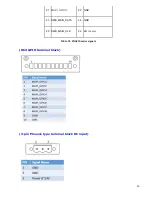
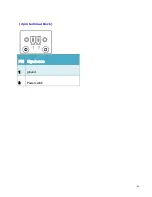
Page 31: ...31 2pin terminal block PIN Signal name 1 ground 2 Powerswitch ...
Page 32: ...32 MITAC Embedded System P150 10AI BIOS Specifiction ...
Page 66: ...66 Help Change the Printer Port mode Comment SKU S did not have Parallel port menu ...
Page 86: ...86 Press Enter when selected to go into the associated Sub Menu ...

