background image

Safety, Operation, & Maintenance Manual 

Linear Cut Processing Systems 

11 


1.3.2.3


Hydraulic or Pneumatic System Lockout/Tagout Procedure 

Before working on or near hydraulic or pneumatic components, bleed the lines of 

pressure. See 

the 

Pneumatic System


section


for further instruction. 


When Lockout/Tagout Is Not Required 

If working on components other than the hydraulic or pneumatic system, but that 

requires you to be near the vicinity of movable hydraulic or pneumatic components, you 

must, at a minimum, physically restrain those components from moving. If this is not 

possible, lockout/tagout the entire hydraulic or pneumatic system. 


When Lockout/Tagout Is Required 


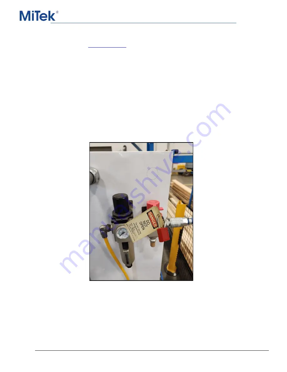
Before attempting repair or performing maintenance on a hydraulic or pneumatic line 

or component, lockout/tagout the machine properly. Follow your company’s approved 

lockout/tagout procedures. 


 Sample of a Lockout/Tagout on a Pneumatic System 


Summary of Contents for Hornet II

Page 1: ... saw Linear Cut Processing Systems MiTek Component Automation 301 Fountain Lakes Industrial Drive St Charles MO 63301 Phone 800 523 3380 Fax 636 328 9218 machinerysupport mii com PN 001079 Creation date 1 1 2023 Created by A Moll Applies to Gen 2 ...

Page 2: ...gout 7 1 3 1 Lockout Tagout Guidelines 7 1 3 2 ElectricalLockout Tagout Procedures 8 1 3 3 Troubleshooting with an Energized Machine 12 1 4 Emergency Stop Buttons Mechanisms 12 1 4 1 Overview and Locations 12 1 4 2 Engaging and Disengaging an E Stop 13 1 4 3 Safety Guards 14 1 4 4 Audible Alerts 14 1 5 Safety Tests 14 1 5 1 Inspecting the Hornet II Saw 14 1 5 2 E Stop Test 14 1 6 Restricted Zone 1...

Page 3: ...h Panes 39 6 4 1 View Menu 40 6 4 2 Arranging Panes 40 6 5 Software Control Buttons Overview 43 6 5 1 Standard Software Buttons 43 6 5 2 Optional Software Buttons for Optional Equipment 44 7 Pre Operation 46 7 1 1 Passwords 46 7 1 2 Pre Operation Software Checks 46 7 2 Pre Operation Physical Checks 47 8 Operation 47 8 1 Start Conditions 47 8 1 1 Homing the Saw Angle 49 8 2 Physical Control Buttons...

Page 4: ... Calibration of the Pusher 69 9 4 2 Calibration of the Angle 71 9 5 Belts 73 9 5 1 Motor Belt Replacement 73 9 5 2 Blade Belt Replacement 76 9 6 Bearings and Lubrication 77 9 6 1 Applying Bearing Lubricant 77 9 6 2 Bottom Plate Printer Rails 81 9 6 3 Support and Tracking Rollers 81 9 7 Saw Blade 82 9 8 Pneumatic System 84 9 8 1 Removing Pressure from the Pneumatic System 84 9 8 2 Filter Main Regul...

Page 5: ...on Maintenance Manual Linear Cut Processing Systems 10 Maintenance Checklists 98 10 1 Safety Notes For Maintenance Checklists 98 10 2 Daily and Weekly Checklist 99 10 3 Monthly Checklist 100 10 4 Annual Checklist 101 ...

Page 6: ...sult in property damage personal injury or even death Personnel must follow all safety procedures and practices to ensure the safest possible operation of this equipment However at no time is this document a substitute for common sense Personnel must ensure that the work environment is safe and free of distractions Indicates an imminently hazardous situation which if not avoided is likely to resul...

Page 7: ...manual Read and follow all safety notes Failure to comply with these instructions may result in economic loss property damage and or personal injury including death Refer to the lockout tagout guidelines on the following pages to safely perform maintenance and troubleshooting of this equipment Observe and obey all safety labels Replace worn labels immediately Use this equipment solely for the purp...

Page 8: ...pment rated for the proper weight This equipment is not for use in a residential area 1 2 4 Keeping a Safe Environment Pay attention to your surroundings Keep children away All visitors should be kept a safe distance from the work area Hazards may not be apparent to individuals unfamiliar with the machine Keep work areas well lit Keep the work area clean and free of any trip or slip hazards Do not...

Page 9: ...e come to a complete stop and all electrical power has been shut off Check for worn or damaged parts regularly Repair or replace them immediately Only use exact replacement parts specified Using unapproved parts may void the warranty and can be a safety risk Keep the hydraulic pneumatic and electrical systems in good working order at all times Repair leaks and loose connections immediately Never e...

Page 10: ...Electrical Safety Notes Do not use any liquids in the interior of electrical cabinets When using solvents on and around the machine remove power to the machine to eliminate the chance of sparking resulting in explosion or fire Wear a respirator approved for use with solvents ...

Page 11: ...Safety Operation Maintenance Manual Linear Cut Processing Systems 6 1 2 7 General Warnings 1 2 8 E Stop Locations Refer to Emergency Stop Buttons Mechanisms for location of E stops ...

Page 12: ...he energy isolating device and the equipment being controlled cannot be re energized or operated until the lockout device is removed Energy sources include electrical mechanical hydraulic pneumatic chemical thermal or other energy In the case of electrical energy sources the main power and control power to the machinery must be turned off and physically locked in the Off position Before performing...

Page 13: ...al enclosure not including work on the electrical transmission line to the machine follow your company s approved lockout tagout procedures which should include but are not limited to the steps here 1 Engage an E stop on the machine 2 Turn the disconnect switch handle to the Off position See Figure 1 1 Figure 1 1 Disconnect Switch in Off Position 3 Attach a lock and tag that meet OSHArequirements ...

Page 14: ...Safety Operation Maintenance Manual Linear Cut Processing Systems 9 Figure 1 2 Sample of a Lockout Tagout Mechanism on an Electrical Enclosure ...

Page 15: ... approved lockout tagout procedures which should include but are not limited to the steps here 1 Engage an E stop on the machine 2 Shut the power to the machine off at the machine s power source which is usually anelectrical service entry panel on the facility wall One example of a locked out power source panel is shown in Figure 1 3 3 Attach a lock and tag that meets OSHArequirements for lockout ...

Page 16: ...n the hydraulic or pneumatic system but that requires you to be near the vicinity of movable hydraulic or pneumatic components you must at a minimum physically restrain those components from moving If this is not possible lockout tagout the entire hydraulic or pneumatic system When Lockout Tagout Is Required Before attempting repair or performing maintenance on a hydraulic or pneumatic line or com...

Page 17: ...ectedly if not de energized Physically restrain any components capable of movement when working on or near those components 1 4 Emergency Stop Buttons Mechanisms 1 4 1 Overview and Locations Ensure all operators and other personnel around the equipment know the location of ALL safety stop Emergency Stop E stop buttons mechanisms and the purpose and proper procedures for using them An E stop stops ...

Page 18: ...o activate an E Stop push on it An E stop will illuminate red in color when engaged 2 To deactivate an E stop pull on the button so it is in the up position and is no longer illuminated 3 To resume operation press the Reset button in the CutBuilder software The reset button can be found on the Infeed Pusher panel ...

Page 19: ...lock the path of parts Remove any that you may find The following locations are especially important o Infeed pusher and squeezer o Outfeed table o Saw chamber 3 Check the physical condition of the Hornet II Saw 4 Remove lockout tagout and return electrical power and pneumatic pressure to the machine 5 Verify the machine has power by checking if E stops are illuminated green 6 Verify all doors are...

Page 20: ...ual Linear Cut Processing Systems 15 5 Pull the E stop to release it The solid red light should no longer be illuminated on any E stops 6 To resume operation press the Reset button on the Infeed Pusher panel in the CutBuilder software ...

Page 21: ...arked so everyone near the equipment can clearly see the area where danger may exist The restricted zone must be marked and maintained so everyone near the equipment can clearly see the area where danger may exist The customer is responsible for marking the restricted zone prior to startup and maintaining the markings so it is clearly visible throughout the life of the machine ...

Page 22: ...cted Electrical hazard It indicates dangerous high voltages inside of an enclosure and or the presence of a power source To reduce the risk of fire or electric shock do not attempt to open the enclosure or gain access to areas where you are not instructed to do so Refer servicing to qualified service personnel only This equipment should be operated only from the type of source indicated on the man...

Page 23: ...ration Maintenance Manual Linear Cut Processing Systems 18 Slip hazard Use of appropriate footwear is required Trip hazard Pay attention when walking in this area Kickback hazard Keep hands clear of cutting parts ...

Page 24: ...gs must not be blocked or covered This equipment should not be placed in a built in installation such as a wall cutout unless proper ventilation is provided because hot temperatures result Operation of this equipment may result in flying debris and excessive noise To reduce the risk of eye injury wear only approved PPE Keep feet away from moving parts Keep hands away from moving parts High pressur...

Page 25: ...al Linear Cut Processing Systems 20 Equipment has automatic restarting capability Lockout tagout on the upstream disconnect before servicing Warning Three man lift required to move this equipment safely Refer to the installation manual ...

Page 26: ...ems 21 The operation of this equipment requires the use of PPE Do not operate without wearing the required protective clothing Refer to manual After installation read the user s guide carefully before operating Follow all operating and other instructions carefully ...

Page 27: ...ckout in a de energized state Lift point In order to decrease the likelihood of damage to the equipment use only the lift points indicated in the manual To reduce the risk of equipment damage or injury to personnel maintain pressure at safe levels Use of lift equipment is mandatory Consult material safety data sheet Unplug equipment before servicing ...

Page 28: ...ners with liquids such as coffee water soda etc on this equipment Do not operate this equipment in a wet environment Do not expose to water No lift point Do not lift this device with a hook crane assembly Equipment damage occurs Refer to the installation instructions Do not use unapproved lubricants in this equipment Do not operate without guards in place Do not discard into the municipal waste st...

Page 29: ...owing NFPA79 NEC Electrical Code Electrical enclosures carry UL 508Aand the CUL for Canada Safety circuit conforms to Category 3 redundant monitoring Conforms mechanically to the following 10CFR 1910 ANSI B 11 19 Declaration of Noise Emissions Decibel level of ambient and machine operation sound levels Ambient 76 dB Machine operation 86 dB ...

Page 30: ...urces Website Visit the MiTek website for up to date information on all MiTek equipment You may also find the following information there The latest revisions of this manual Services bulletins pertaining to your equipment Support safety and training information Part numbers for ordering parts Contact Us MiTek Automation Customer Support 301 Fountain Lakes Industrial Drive St Charles MO 63301 Parts...

Page 31: ... labeling device Saw unit C The part of the machine that houses the saw blade Edge printer D A device used to perform labeling or place other information onto the part being processed Outfeed table G Area where processed items feed onto after being processed Operator Interface or HMI H A touch screen computer with CBA installed that is used for the operator to acquire and deliver information to an...

Page 32: ...r and advances 1 piece or stack at a time for automatic loading onto the Infeed Rail Outfeed sweep arm assembly F A combination of a steel top table and sweep arm on the outfeed that automatically moves processed boards onto the table to be removed by the operator 4 3 Dust Extraction Methods One port is available for dust extraction from the saw chamber It is highly recommended that a dust extract...

Page 33: ...Safety Operation Maintenance Manual Linear Cut Processing Systems 28 The four valves from top to bottom are Hood Safety Block Hold Down Stroke ...

Page 34: ...9 There is an additional air valve assembly on the back of the gatekeeper assembly The valves include Sweeper if equipped Squeezer Bottom plate printer if equipped Counter balance See the Pneumatic System section for more information on pressures and how to adjust them ...

Page 35: ...e also two status lights one red one green and a reset button Controller The controller is comprised of two boards and connects to the pen stalls via the ribbon cables Ribbon Cables Cables that connect the pen stalls to the controller Pen Stalls Stalls that house the ink cartridges They are spring loaded and feature a clip for securing the ink cartridges Ink Cartridges Replaceable cartridges that ...

Page 36: ...nance Manual Linear Cut Processing Systems 31 5 1 Print Areas 5 1 1 Reading the Printed Data The following figures identify the different informational items that can be printed by the edge or bottom plate printer if equipped ...

Page 37: ...ear Cut Processing Systems 32 5 1 2 Modifying the Printed Data To modify the printed data settings click on the printer on the saw picture on the top panel of the CutBuilder software then click on Print Marking to open the Print Marking menu ...

Page 38: ... Processing Systems 33 5 2 Controller The controller is comprised of two boards with a bushing between them The top board of the controller features four slots for ribbon cables Each slot is labeled one through four and corresponds with a pen stall ...

Page 39: ...To open a ribbon cable slot pull the black clip away from the slot To secure it push the black clip back into place 5 3 Ribbon Cables Each printer housing has four ribbon cables The ribbon cables connect the pen stalls to the controller and must be unseated on both the controller and pen stall end to be removed ...

Page 40: ...pen stalls that house the ink cartridges Each pen stall is connected to a corresponding slot on the controller with a ribbon cable When facing the pen stalls from the front of the enclosure the pen stall closest to the back of the enclosure is number four and the pen stall positioned closest to the front is number 1 ...

Page 41: ...anels with five of them customizable Home Screen Panels Menu Bar Features the My Jobs View Help Settings and Shut Down functions It also features a System Status and Doors E Stop indicator Top Panel Features an image of the saw that is interactive Clicking on certain parts of the image will bring up the corresponding settings menu Left Panel Center Panel and Right Panel Three different horizontal ...

Page 42: ...home screen panes can be accessed by using the View menu on the Menu Bar The available home screen panes are Jobs Displays the currently loaded jobs Bundles Displays the available bundles for the currently selected jobs Materials Material Type Displays materials that can be selected to use for the cut sets ...

Page 43: ...Safety Operation Maintenance Manual Linear Cut Processing Systems 38 Part Types Displays the different part types that are included in the selected job and bundle Cut Lengths Cut Parts ...

Page 44: ... as they are processed Infeed Auto Loader Displays additional controls for the Auto Loading Live Deck if equipped Outfeed Ejecting System Displays additional controls for the outfeed sweeper arm if equipped 6 4 Customizing the Home Screen Panels with Panes The home screen panels excluding the Menu Bar and Top Panel can be configured freely using the different panes ...

Page 45: ...ndicates that the panes are locked Click on the Lock Panes option to remove the checkmark and allow the panes to be moved freely Save Pane Layout is used to save the current pane layout as the default Note that only one pane layout can be saved at a time Reset Panes can be used to go back to the last saved pane layout 6 4 2 Arranging Panes To arrange panes start by ensuring the panes are not locke...

Page 46: ...to move and begin to drag it to the panel you would like to move it to The following pane pinning icons will appear When hovering over a pane pinning icon a transparent box will appear showing a preview of where that pane will display when dropped Below is an example of the preview when hovering over the left arrow pane pinning icon ...

Page 47: ...Safety Operation Maintenance Manual Linear Cut Processing Systems 42 When the pane is in the desired position as indicated by the preview release the left click to drop the pane in that position ...

Page 48: ...ual for using manual operations such as moving pusher to a given location jogging the pusher forward or backward and other manual type of operations Modes Cut Sets Changes the operational mode to Cut Set mode which is used for optimized cutting of full stock lengths into shorter cut lengths Operations Load Set Available when in Cut Set mode Pressing Load Set does the following 1 Sends the push arm...

Page 49: ...ard or backward by a distance entered by the operator 6 5 2 Optional Software Buttons for Optional Equipment The optional software control buttons that appear in the CutBuilder are affected by which panels are currently displayed See the Home Screen Panes section for more information 6 5 2 1 Infeed and Outfeed The Infeed Loader and Outfeed control buttons are only available if equipped and if the ...

Page 50: ...d Test Kickers Out In Used to for testing purposes only to check functionality of all pneumatic kicking mechanisms Pressing Test Kickers Out will execute all kickers to extend out Pressing Test Kickers In will retract the kickers back to their normal position Note The system does not allow running the outfeed with the kickers extended out nor should the operator attempt to run the system with the ...

Page 51: ...on Software Checks 1 If the computer is not already on start the computer by pressing its power button 2 Confirm that the PC is on and at the Windows login prompt by visually inspecting the screen on the computer monitor in the HMI 3 Login to Windows with your company assigned Windows username and password 4 Wait until all obvious startup activity has completed and the cursor is ready for use befo...

Page 52: ...the front of the inkjet cartridges 2 If any noticeable damage to any cartridges is found replace the cartridge 3 Clean purge and test the printer 8 Operation 8 1 Start Conditions Powering Up the Motor Controls The motor controls for the pusher must be powered on before operation may begin The button for powering on the motor controls can be found on the bottom panel of the CutBuilder software Homi...

Page 53: ...r Once the pusher reaches the homing sensor it will move the opposite direction away from the sensor Then the pusher resets its internal reference and the pusher s homing is completed 2 A Homing successful message will appear when homing the pusher is complete NOTE For efficiency always home the pusher before homing the saw ...

Page 54: ...plish homing the saw angle 1 To begin homing the saw angle open the Saw Menu by clicking on the saw in the top panel in the CutBuilder software 2 Enter the machine password if prompted 3 Click the Home button 4 The grooves on the saw angle table should align with those on the saw table If they do not perform a calibration of the angle See the Maintenance section for more information on calibration...

Page 55: ...sequence If there is an active cut sequence the saw completes the cut sequence then moves to the optimized position ready for the next cut Pressing the Pause button again resumes operation FWD Pressing and holding the button causes the chains to progress towards the infeed pusher REV Pressing and holding the button causes the chains to progress away from the infeed pusher Start Starts the current ...

Page 56: ...et Resets the saw after a fault Has the same function as the Reset button in the CutBuilder software Saw Stop Halts all movement on the saw Using Saw Start will not resume activity The saw must be reset to proceed Saw Start Starts the saw from a stopped state Pause Halts all movement of the saw Saw Start will resume activity Pusher Go Resumes movement of the pusher from a Saw Stop or Pause state ...

Page 57: ...cation or moving forward or reverse for a given distance The button for manual mode can be found on the bottom panel of the CutBuilder software 8 3 1 Relative Move Pusher Distance The Relative Move function is used to move the pusher either forward or backward a specified distance To begin moving the pusher press the Relative Move button available on the Infeed Pusher menu ...

Page 58: ...near Cut Processing Systems 53 The Relative Move Infeed Pusher window will appear Speed and distance can be set in increments All increments are in motor steps Toggling the right or left direction buttons will move the push arm accordingly ...

Page 59: ...elect Go to execute and the pusher will move to the position entered The distance is measured from the saw blade Select Park to quickly move the infeed pusher to its park position which is at the end of the infeed conveyor farthest away from the saw blade The exact location can be adjusted using the Load Offset setting in the Infeed Pusher Settings screen The Infeed Pusher Settings can be displaye...

Page 60: ...Manager Cut Set mode is used for cutting entire lists of cut items from long stock lengths for optimal usage of material 8 4 1 Job Manager Jobs are managed by using the Job Manager menu To access the Job Manager menu press the My Jobs button located on the Menu Bar The Job Manager will open ...

Page 61: ...ger window Navigate to the desired file and click Open to load it Online Jobs Online Jobs can be used to load files from an online location if configured File Types Cut Sets can be imported as one of these types xml files is generated from MiTek production software Can also be called a Virtek LaserMC file ehx is generated by MiTek Production software including ShopNet software wbx ...

Page 62: ...ized has print labels etc To create a manual cut list click on Manual List in the Job Manager menu Build a cutting list by selecting desired material and entering length quantity then click Add to List Click Exit when finished Edit List The Edit List function can be used to edit any current loaded job Batches may be added manually by using the same technique as Manual Entry Batches can also be del...

Page 63: ...he Job Manager displays jobs that are Active Click the drop down menu then Trash to see jobs that have been deleted Click the Completed button to see jobs that have already been processed To delete a job or move it to the trash left click the job and drag it to the trash can icon A dialog box will display asking for a confirmation The job will be moved to the Trash location ...

Page 64: ...he specific panes For example A job contains all the parts of a house and has many different dimensional lumbers in use You want to cut only the part types that are 2x4s used for Bottom Plates and Top Plates Place toggles on those items as shown below and the cutting solution will only include those items in the cutting mix When you want to cut the rest of the items simply follow the same principa...

Page 65: ...ze one or many different stock lengths When multiple stock lengths are chosen the optimizer will use all selected lengths and produce cut sets based upon whichever stock length would produce the least waste for each cut set created If the desired stock length is not listed add to or edit the stock length library by clicking the Lengths button in the lower left of the window to access the editor On...

Page 66: ... 61 8 4 4 Optimizing Material After all of the appropriate selections have been made press the Optimize button and the cutting solution will appear in the Cut Sets panel Optimizing processes all selections and generates the cut sets to have the least amount of waste ...

Page 67: ...nually indicate an active cut set select it by clicking anywhere there is text in the Cut Set row 2 View Cut Part Details and Printed Image Click the board image and the Cut Part Details screen displays details about the Cut Set and shows an image of the printing that part will receive 3 Complete Incomplete During normal operation the Hornet will automatically complete each cut set as it runs On r...

Page 68: ...te when this is necessary Load 2x lumber stacked 2 high on infeed conveyor Can also cut 2x lumber as a single board Lumber thicker than 2x dimensional lumber can only be cut 1 board high Ensure the boards used o Have no staples and no standing water on them Staples can damage the print heads o Are not tight up against the pusher when placed on the infeed rail o Are tight up against the fenceline w...

Page 69: ...zer when attempting to ensure the boards remain flush with each other 8 5 2 Cutting Procedure Overview 1 Select the Cut Sets button on the bottom panel 2 Select the Load Set button The Cut Set Operations window appears and the next batch of Cut Sets are imported NOTE If the Load Set button does not appear ensure there are cut sets populated See the Populating Cut Sets from a Specified Job section ...

Page 70: ...ears 6 Click Cut Complete and the next Cut Set is loaded 7 Once all Cut Sets are cut press Quit 8 Press the Reset button 9 Press the Load Set button again to import another batch of Cut Sets 8 6 System Settings Accessing the Device Settings Windows Most settings can be accessed by clicking the appropriate component in the Top Panel Note that there is no undo or save function the new settings are a...

Page 71: ...Safety Operation Maintenance Manual Linear Cut Processing Systems 66 Most settings can also be accessed via the Settings menu on the Menu bar ...

Page 72: ...ance and preventive maintenance Additional maintenance instruction and videos can be found on our web site or video storage site Read the safety section starting on page 1 The safety test procedures in the safety section MUST be performed by qualified personnel after ANY maintenance adjustment or modification Note these safety reminders Note the proper way to clean inside an enclosure ...

Page 73: ...al Equipment section 9 3 Cleaning and Inspecting 9 3 1 Cleaning If it should become necessary to clean this machine disconnect it from its power source first Do not use liquid cleaners aerosols abrasive pads scouring powders or solvents such as benzene or alcohol Use a soft cloth lightly moistened with a mild detergent solution Make sure the surface cleaned is fully dry before reconnecting power 9...

Page 74: ...machine password if prompted 2 The infeed pusher settings will open Select Calibrate 3 A dialog box will open with a brief explanation of the calibration process Click OK to start the homing process 4 Another dialog box will appear that explains the scaling process Once homing is complete measure from the edge of the pusher to the edge of the physical saw blade then click OK The Enter Measurement ...

Page 75: ...the edge of the pusher to the edge of the physical saw blade in the Enter Measurement dialog box then click OK The Jog Infeed pusher dialog box appears 6 Using the Relative Move infeed pusher menu adjust the pusher manually by choosing the increment to move then the left or right button accordingly ...

Page 76: ... 4 2 Calibration of the Angle 1 A calibration is needed if the groves on the angle table are not matched up with the rest of the table after homing the saw angle Below is an example of the groves matching up accordingly Note that they may not align exactly due to wear and different saw configurations 2 To begin the calibration process open the saw menu by clicking the saw graphic on the top panel ...

Page 77: ...er adjusting the number home the saw again and check if the grooves are aligned If they are not continue to repeat steps 1 through 3 until they are aligned NOTE The Hard Stop Home Offset number should not be configured below 11 700 or above 12 300 If adjustment beyond this range is necessary there is likely a problem beyond calibration such as a loose belt In the following example figure increasin...

Page 78: ...ay need to be replaced if it becomes worn or as directed by MiTek Automation Support To replace the motor belt use the following procedure 1 Lockout tagout 2 Remove the guard between the motor and saw blade by removing the bolts indicated in the next figure 3 Loosen the motor bolts and the side shaft belt until the belt is loosened enough for removal Ensure not to loosen the bolts so much that the...

Page 79: ... 2 FHCS that attaches to the bearing 5 Remove the motor side bearing bolts from the top side and then remove the 1 2 aluminum spacer that is between the bearing and the tabletop Also loosen the bolts indicated below which will cause the pivot shaft assembly to droop this is to assist in belt replacement There is no need to remove any bearings from the shaft ...

Page 80: ...t direction 7 Re tighten the motor bolts and side shaft bolt as needed to tension the belt 8 Spin the hub by hand to ensure nothing is binding or needs to be adjusted before re assembly 9 Re install the guard between the motor and blade tighten and install any bolts as needed from the pivot assembly and replace the stainless steel topper on the round table ...

Page 81: ...too short to be removed from the pulley while the pulley is still mounted 3 Install the new belt in the appropriate position 4 Re install the shaft pulley Ensure that the spacer bushing is between the taper bushing and bearing Placing the taper bushing against the spacer ensures proper belt alignment 5 Pry the tensioner indicated in the figure below to adjust the belt tension The play for the blad...

Page 82: ... Gather the following materials a Manual grease gun b No 2 lithium based grease 2 Lockout tagout 3 Locate the grease fitting on the bearing The following sections provide guidance on the grease fitting locations depending on the part 4 Clean the fitting thoroughly to remove any dirt or old grease 5 Place the manual grease gun over the fitting 6 Add grease to the bearing until you feel resistance A...

Page 83: ...Safety Operation Maintenance Manual Linear Cut Processing Systems 78 Motor Arbor and Pivot Bearings Motor arbor and pivot bearing locations ...

Page 84: ...Safety Operation Maintenance Manual Linear Cut Processing Systems 79 Auto Loading Live Deck Auto Loading Live Deck bearing locations Auto Loading Live Deck drive shaft location ...

Page 85: ...ed Table w Sweeper Assembly Sweeper assembly if equipped bearing locations Squeezer Arm The squeezer arm bearings are located behind and under the front plate embossed with CSP The front plate is transparent to make the bearing locations easier to see in the following figure ...

Page 86: ...f equipped has rails on either side that should be lubricated 9 6 3 Support and Tracking Rollers The stainless toppers must be removed to access the support and tracking rollers The rollers should be lubricated as needed to ensure smooth operation Support and tracking rollers location shown with the toppers and saw guard removed ...

Page 87: ... rotates upward towards the saw table Specs for Replacement Blades A replacement blade must meet the following criteria 20 Blade Diameter 180 Kerf 80 of teeth 10 Hook Angle 0 Face Angle When to Replace the Saw Blade The frequency of blade changes and of repairs also depends on the number of hours the saw is running each week Check the saw blade weekly for signs of wear and replace accordingly ...

Page 88: ... saw blade 3 8 12 point socket Torque wrench driver 2 Activate an E stop and lockout tagout 3 Open the front saw chamber door to access the blade 4 Remove 4 bolts holding saw blade 5 Remove saw blade and set aside for safe disposal 6 Place the new saw blade on the hub 7 Tighten the bolts to the torque specification of 30 ft lbs ...

Page 89: ...c system require the removal of pressure Use the following procedure to remove pressure from the system 1 Turn the switch to the off position by turning it counterclockwise while applying downward pressure The lockout tagout hold will move into a position where a lockout tagout can be used Red Pneumatic Switch in the Open Position 2 Lockout tagout through the hole on the slide ...

Page 90: ...Safety Operation Maintenance Manual Linear Cut Processing Systems 85 Red Pneumatic Switch in the Lockout Position Red Pneumatic Switch with a lockout tagout ...

Page 91: ...operating pressure for a pneumatic system The following table lists the necessary operating pressure for the different regulators Regulator Action PSI Main 80 Bottom Plate Printer 40 Squeezer 40 Counter Balance 40 Note that these pressures may need to be slightly adjusted for proper operation 40 PSI is the recommended starting point Adjusting the Pressure on the Main Regulator The main regulator i...

Page 92: ...he knob in a clockwise direction to increase pressure Turn the knob in a counterclockwise direction to decrease pressure 2 Once the desired pressure has been reached stop turning the knob then push down to secure it in place and lock the pressure Adjusting the Pressure on Additional Regulators There are two additional regulators located on the front of the gatekeep assembly There may be a third if...

Page 93: ...pposite from the main regulator The pressure indicator also reads inverted 1 Pull down and then turn the black knob of the desired regulator to adjust the pressure The gauge on the front of the regulator indicates the current pressure Turn the knob in a clockwise direction to decrease pressure Turn the knob in a counterclockwise direction to increase pressure 2 Once the desired pressure has been r...

Page 94: ...oved if it malfunctions or if directed by MiTek Automation Support 1 Lockout tagout 2 Ensure the printer is completely powered off before opening the printer enclosure 3 Remove the USB and DB 15 cables from the top of the enclosure if working with the bottom plate printer If working with the edge printer remove the cables from the back of the enclosure ...

Page 95: ...hat go between the controllers if they become separated 9 9 2 Removing the Pen Stalls One or multiple pen stalls may need to be removed if they malfunction or if directed by MiTek Automation Support Use the following procedure to remove and or replace a printer pen stall 1 Lockout tagout 2 Start by completely removing the ribbon cable connected to the pen stall to be removed 3 Ensure the printer i...

Page 96: ...lled or deionized water or use a wet wipe Ensure it is not dry as a dry cloth may cause scratches You may wish to fold the cloth in quarters to prevent ink penetrating through to your fingers 4 Dab lightly one at a time on the face of the nozzles of each of the cartridges Be careful not to push too hard as the cartridge could become unseated from inside its stall and cause damage to the printer 5 ...

Page 97: ...artridges emit a burst of ink spray onto the scrap wood paper NOTE the saw must be powered on to use the Ink Spit function The Ink Spit button is located in the CutBuilder software on the top panel 9 Successful preparation of the inkjet printer is completed when a full vertical line of ink is present for all cartridges Repeat steps 2 through 5 until successful preparation of all cartridges is achi...

Page 98: ...en stall assembly while the printer enclosure is powered on 2 Lift the lever on the pen stall housing the ink cartridge intended for replacement 3 Gently pull up on the corner closest to the pins to remove the cartridge 4 To replace a cartridge gently insert it at an angle where the far end drops into the carriage first 5 Once the cartridge is seated return the lever to a closed position to secure...

Page 99: ...tions in the Removing and Replacing Ink Cartridges section 4 Use the Ink Spit function to make all the ink cartridges emit a burst of ink spray onto scrap material Ensure all cartridges emit a clear dark line See Removing and Replacing Ink Cartridges for more information 9 9 4 3 Storage and Environment Operating temperature of ink 13 35 C 55 95 F Storage transportation temperature anytime a cartri...

Page 100: ...asis or as needed based on visibility It is recommended that the window be cleaned using a common glass plastic cleaner The window should be sprayed and wiped down with a soft cloth to prevent damage to the surface Do NOT use benzene acetone or a thinner as it will damage the surface Squeezer Sensor The Squeezer Sensor verifies presence of material in front of the squeezer before it engages The Sq...

Page 101: ...indow should be sprayed and wiped down with a soft cloth to prevent damage to the surface Do NOT use benzene acetone or a thinner as it will damage the surface 9 10 2 2 Proximity Sensors Proximity sensors 5 that detect material or that an enclosure is closed are located along the length of the machine Check the locking nuts and sensor tightness every 6 months Home Sensor Over Travel Sensor Edge Pr...

Page 102: ...Safety Operation Maintenance Manual Linear Cut Processing Systems 97 ...

Page 103: ...p working condition These pages are supplied with the intent that you will photocopy them and leave the original in the manual for future use Space is provided in each chart to place the date that the work is done and the initials of the person performing the work 10 1 Safety Notes For Maintenance Checklists Daily Weekly Checklist pg 99 Monthly Checklist pg 100 Annual Checklist pg 101 Checklist Pa...

Page 104: ...ing Live Deck Infeed Pusher Saw Unit and outfeed table Daily Vacuum Saw Unit Daily Clean printer nozzles and test printers 2x Day Inspect linear guide bearing rails for grease bottom plate printer only Weekly Replace saw blade Weekly Insect the squeezer photo eye and clean as needed Weekly Inspect sensors for debris and or excessive buildup Weekly Grease motor arbor bearings and motor pivot bearin...

Page 105: ...arm 3 months Check oil level in all gearboxes 3 months Auto Loading Live Deck drive shaft bearings grease 6 months Proximity Sensors check locking nuts and sensor tightness 6 months Action Interval JULY AUG SEP OCT NOV DEC Check Auto Loading Live Deck alignment 1 month Inspect and apply grease as needed to the saw table support and tracking rollers 1 month Grease 2 fittings on elevation jack screw...

Page 106: ...ual Checklist Hornet II Year ___ Action Interval Sign and Date When Action is Performed Auto Loading Live Deck motor gearbox grease 1x year Auto Loading Live Deck drive shaft grease 1 fitting per strand 1x year Lubricate squeezer arm bearings 1x year Inspection 1x year Notes Date ...

Reviews: