Installation
129
Aastra 470 as of R3.2
syd-0337/1.6 – R3.2 – 09.2014
4. 7. 3
Terminal interfaces
4. 7. 3. 1
DSI terminal interfaces
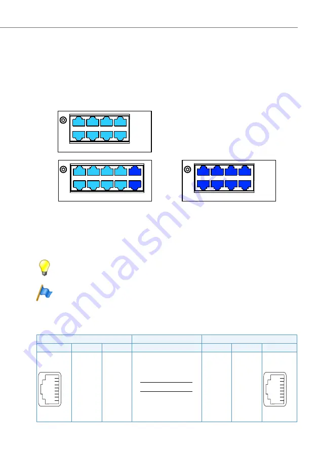
Fitting the corresponding interface cards means that DSI terminal interfaces are
available on the RJ45-sockets on the front panel of the cards. The possible RJ45
sockets are highlighted in colour in the figure below.
Fig. 45
Connection possibilities for DSI terminal interfaces
On terminal cards with 16 or more interfaces some or all of the RJ45 sockets are
multiply assigned. The signals can be split again to individual RJ45 sockets using
patch cables and the fan-out panel FOP (see
) or with
8-fold assigned connecting cables (see e.g.
Prefabricated system cable 4 x RJ45
Tip
Multiply assigned RJ45 sockets are colour-coded in blue.
Note
Circuit type as per EN/IEC 60950: SELV
Connection
Tab. 57
Connection of individually assigned DSI terminal interface
Communication server
Cable cores
Connection socket
Socket
Pin
DSI signal
DSI signal
Pin
Socket
1
–
–
1
2
–
–
2
3
–
–
3
4
a
a
4
5
b
b
5
6
–
–
6
7
–
–
7
8
–
–
8
%4*
%4*
%4*


