MITSUBISHI ELECTRIC 1100B SERIES UPS
1100B SERIES UPS
OWNERS / TECHNICAL MANUAL
Page Number:
2-11
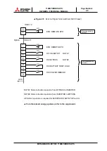
Refer to Figure 30 for a typical wiring configuration. Although this figure applies to the
remote start/stop terminals, the same wiring arrangement is used for emergency stop,
power demand and battery temperature high.
Figure 30
Remote "Start" Contact Connections
Details of input contacts for remote access: IOAU-12
Terminals 3 to 4
"Remote EPO" contact input
Used to perform a remote UPS Emergency Power Off (EPO).
The load will be dropped.
NOTE: The UPS is equipped with a selectable input contact item.
The above items are the default settings. Contact MITSUBISHI
ELECTRIC POWER PRODUCTS, INC for setup information at
1-800-887-7830.
CAUTION: In all cases, a switch having a protective cover is recommended in
order to reduce the possibility of accidental operation.
CAUTION
Relay Coil current: 10mA
Switches Only
Start
Use Momentary
UPS Cabinet
External to
UPS Cabinet
Relay
Coil
24
VDC
Start
Switch
Common
0.5S - 4S
ON
OFF
User supplied
!
NOTE
Summary of Contents for 1100B Series
Page 2: ...Preface ...
Page 64: ......


