


16
NP180/160 Series Setup Manual
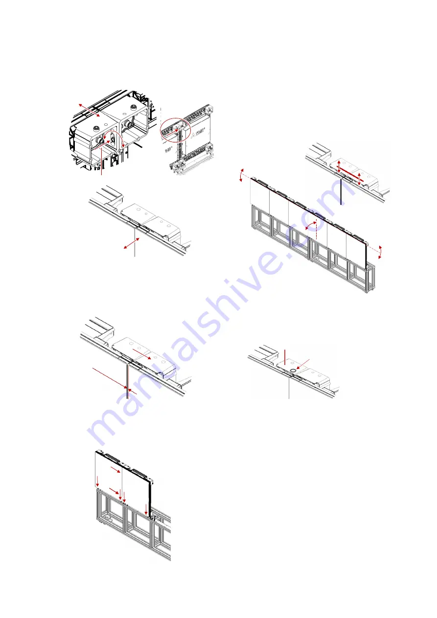
Adjustment screw
Gap width
Horizontal
fixing screw
6.
Insert another adjustment screw on the top
border of the two LED units and turn the screw
to align the upper LED surfaces of the LED units
to be flat.
7.
Carefully tighten two horizontal fixing screws to
make the vertical gap and the surface flatness
between the two LED units evenly minimized.
The target of the surface flatness adjustment is
0.1 mm or less.
The gap width can be more recognizable if you
light up the LED units (p. 21).
8.
Fix rest of the fixing screws tightly.
9.
Repeat the steps to mount all the bottom row
LED units.
10.
Prior to mounting the second bottom row,
recheck the level and leaning of the LED units
as well as the linearity of the upper surfaces of
the units. Readjust them if inaccurate. The
targets are 0° level and
±
0.5° or less leaning
measured with the digital level.
If there is no way to match the height of
adjacent corner blocks, lay a thin spacer (p. 6)
such as shim rings to align the level of the top
surfaces.
11.
When the back space is narrow with the front
maintenance models, temporarily place the
cables from the lower LED units where you can
reach as light clamping for the ease of
connecting to the upper LED units.
Thin spacer
(Place it near
the LED surface.)
Corner block
Summary of Contents for 12NP180 Series
Page 50: ......


