20
NP180/160 Series Setup Manual
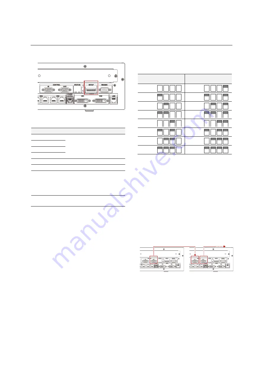
DIP switch on control unit
Set the DIP switch on the control unit adequately
according to system configurations.
Cycle the main power switch to apply the
change.
No. Name
Function
Default
1
IP address
The low 4 bits in the IP
address
Off
2
IP address
3
IP address
4
IP address
5
Reserved
No use
Off
6
F/W update
for factory use
Off
7
Default IP
address
On: fixed as 192.168.100.XX
The range of XX is 32 to
47, which follows the
switch #1 – 4 setting.
Off: alterable
Off
8
Master/slave
On: master
Off: slave
Off
IP address, ID assignment
A unique IP address and an ID number can be
assigned on each control unit for controlling
through network. The initial setting is 192.168.100.32
and ID 1.
1.
Be sure the DIP switch #7 is OFF.
When the DIP switch #7 is ON, the IP address
on the control unit is fixed as 192.168.100.XX.
The last byte (the part of “XX”) follows the
setting of the DIP switches #1 to 4 in the range
of 32 to 47. It can be used when the specified
IP address is unclear and you can’t hook up.
2.
With the DIP switches #1 to 4, the last byte of
the IP address can be set in the range of 32 to
47. The ID numbers are automatically assigned
linked with the setting.
Last
byte
ID 1 2 3 4
Last
byte
ID 1 2 3 4
32
1
40
9
33
2
41
10
34
3
42
11
35
4
43
12
36
5
44
13
37
6
45
14
38
7
46
15
39
8
47
16
The last byte of the IP address can be set other
than that range as well combining with the “LAN
setting” menu in Wallaby (p. 32). The menu can
also change other upper bytes in the address.
The ID numbers can be extended up to 64 with
the “ID number” menu in Wallaby (p. 32).
Master/slave setting
When you use multiple control units in an LED wall
(p. 12), set a control unit as “master” with the DIP
switch #8. The master unit directs other slave units.
The initial setting is slave.
Master
Slaves
Summary of Contents for 12NP180 Series
Page 50: ......


