Electrical adjustment
21
Turning-on
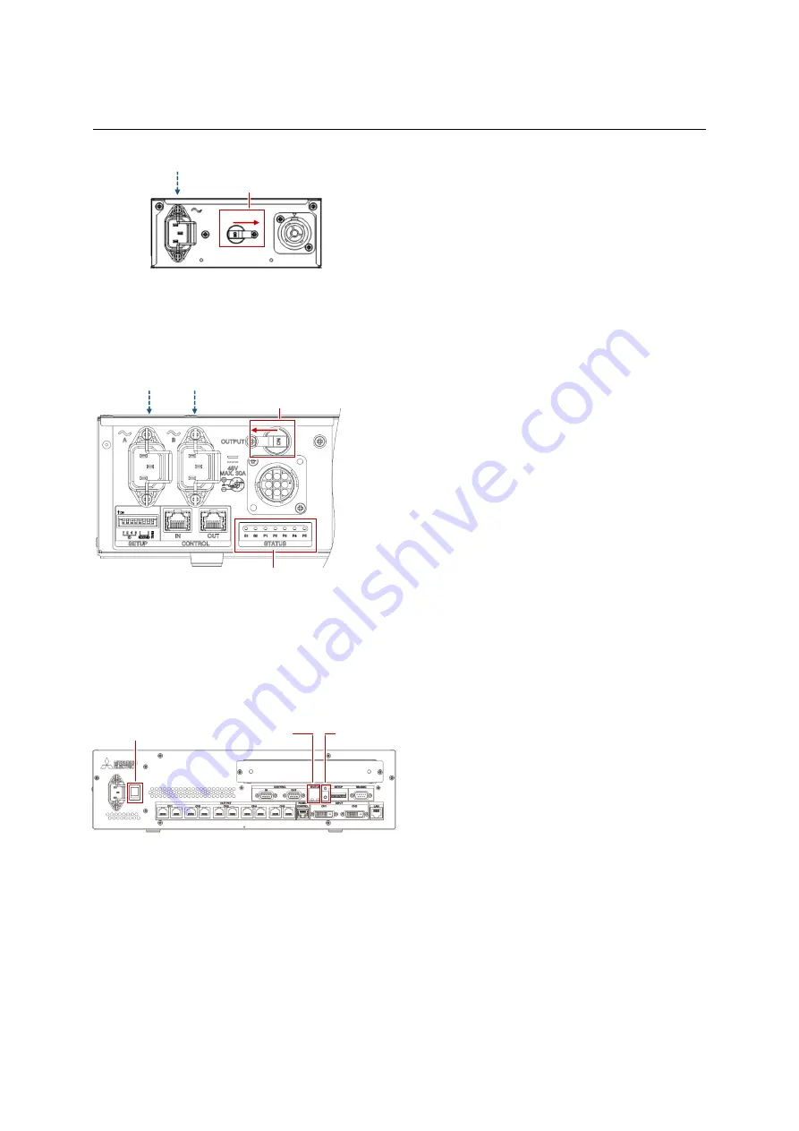
Adapter (180 Series)
1.
Be sure that the breaker on the adapter is ON.
2.
Connect an AC power cord to the 3-pin power
socket.
Power unit (160 Series)
1.
Be sure that the breaker on the power unit is
ON.
2.
Connect two AC power cords to the 3-pin
power sockets. The indicators, S1 and S2, start
lighting to indicate the standby state (p. 48).
Control unit
1.
When you turn on the main power switch, the
two status indicators start lighting in blue
showing starting up process (p. 48). It takes
about 1 minute for the standby state and
changes to one green indicator.
2.
To supply the power to the connected LED
units, follow either way.
A.
Press the power button on the control unit.
B.
Click “On” button in “Power” menu in
Wallaby (p. 24).
C.
Set the “Auto power on” function ON in
Wallaby (p. 33). The power is automatically
supplied when the control unit is turned on.
3.
Once the power is supplied, the two indicators
light in green. The LED units remain in black
The image is displayed when an image source
has been connected.
When the active power peak saving function (p.
33) is to be used due to lower total power
distribution to the system, set the function ON
prior to the image displaying. If an image is
displayed in OFF setting, the power
consumption may exceed the power supply
and the breakers in the power distribution may
trip depending on the contents of the image or
internal test patterns (p. 38) to be displayed.
The OPS computer also starts booting up if you
have.
A white pattern will be displayed on LED units if
the image signal cable connection (p. 10) is
incorrect. Check the cabling in this case.
Main power switch
Power button
Indicator
Breaker
Breaker
Indicator
Summary of Contents for 12NP180 Series
Page 50: ......


