background image

44

4.  EMC AND LOW VOLTAGE DIRECTIVES

Compliance to the EMC Directive, which is one of the EU Directives, 
has been a legal obligation for the products sold in European countries 
since 1996 as well as the Low Voltage Directive since 1997.
Manufacturers who recognize their products are compliant to the EMC 
and Low Voltage Directives are required to attach a "CE mark" on their 
products.

(1) Sales representative in EU member states

Authorized representative in Europe is shown below.
Name: MITSUBISHI ELECTRIC EUROPE B.V.
Address: Mitsubishi-Electric-Platz 1, 40882 Ratingen, Germany

Summary of Contents for 13J240

Page 1: ...c programmable controller MELSEC L series 2009 MITSUBISHI ELECTRIC CORPORATION Safety Guidelines Prior to use please read this and relevant manuals thoroughly to fully understand the product MODEL LCPU U HW MODEL CODE 13J240 IB NA 0800456 P 1806 MEE ...

Page 2: ...al in a safe place for future reference All safety precautions for the MELSEC L series products are described in this manual Design Precautions WARNING Configure safety circuits external to the programmable controller to ensure that the entire system operates safely even when a fault occurs in the external power supply or the programmable controller Incorrect output or malfunction due to a communi...

Page 3: ...may turn on if an error occurs in a part such as an I O control part where the CPU module cannot detect any error To ensure safety operation in such a case provide a safety mechanism or a fail safe circuit external to the programmable controller For a fail safe circuit example refer to GENERAL SAFETY REQUIREMENTS in this manual 5 Outputs may remain on or off due to a failure of an output circuit r...

Page 4: ...n absolute position return by the CPU module s positioning function may turn off the servo on signal servo off for approximately 20ms and the motor may run unexpectedly If this causes a problem provide an electromagnetic brake separately to lock the motor during absolute position return Do not write any data to the system area or write protect area R of the buffer memory in an intelligent function...

Page 5: ...ed Deceleration starts when the near point watchdog signal turns on If an incorrect OPR direction is set motion control may continue without deceleration To prevent machine damage caused by this configure an interlock circuit external to the programmable controller 2 When the module detects an error the motion slows down and stops or the motion suddenly stops depending on the stop group setting in...

Page 6: ...sult in malfunction due to noise During control of an inductive load such as a lamp heater or solenoid valve a large current approximately ten times greater than normal may flow when the output is turned from off to on Therefore use a module that has a sufficient current rating Time from when the CPU module is powered on or is reset to when it enters in RUN status depends on the system configurati...

Page 7: ...mable controller is on Failure to do so may result in incorrect output or malfunction Precautions for using flexible high speed I O control modules Do not install the control lines or communication cables together with the main circuit lines or power cables Keep a distance of 150mm or more between them Failure to do so may result in malfunction due to noise WARNING Shut off the external power supp...

Page 8: ...cause malfunction Keep in mind that there is a possibility that the unit is high temperature during turning on electricity and immediately after power supply interception Do not directly touch any conductive part and electronic components of the module and the SD memory card Doing so can cause malfunction and failure of the module and the SD memory card WARNING Shut off the external power supply f...

Page 9: ...r cables Keep a distance of 100mm or more between them Failure to do so may result in malfunction due to noise Place the cables in a duct or clamp them If not dangling cables may swing or inadvertently be pulled resulting in damage to the module or cables or malfunction due to poor connection Confirm the interface type in advance and connect the cable correctly Connecting a cable to a different in...

Page 10: ...d in control panels Connect the main power supply to the power supply module in the control panel through a relay terminal block Wiring and replacement of a power supply module must be performed by qualified maintenance personnel who is familiar with protection against electric shock For wiring methods refer to the MELSEC L CPU Module User s Manual Hardware Design Maintenance and Inspection Precau...

Page 11: ... machines or cause accidents Do not disassemble or modify the modules Doing so may cause failure malfunction injury or a fire Use any radio communication device such as a cellular phone or PHS Personal Handy phone System more than 25cm away in all directions from the programmable controller Failure to do so may cause malfunction Shut off the external power supply for the system in all phases befor...

Page 12: ...ondition Precautions for using flexible high speed I O control modules Before performing online operations for the running module from the personal computer connected read relevant manuals carefully and ensure the safety Before changing each setting of the module read relevant manuals carefully and ensure the safety and change the status of the CPU module to STOP CAUTION When controlling a running...

Page 13: ...rding to the local regulations For details of the Battery Directive in EU member states refer to the MELSEC L CPU Module User s Manual Hardware Design Maintenance and Inspection CAUTION When transporting lithium batteries follow the transportation regulations For details of the regulated models refer to the MELSEC L CPU Module User s Manual Hardware Design Maintenance and Inspection ...

Page 14: ...référer autant que de besoin Toutes les précautions de sécurité à observer pour les produits de la série MELSEC L sont présentées dans ce manuel Précautions lors de la conception AVERTISSEMENT Configurer des circuits de sécurité extérieurs à l automate programmable pour garantir la sécurité du système dans son ensemble à la survenance d une anomalie dans l alimentation externe comme dans l automat...

Page 15: ... hors service par le paramétrage Toutes les sorties pourraient rester actives si l erreur s est produite dans une partie comme un organe d entrée sortie dont le module CPU ne peut pas détecter les erreurs Pour garantir la sécurité en exploitation dans un telle éventualité il faut donc prévoir un mécanisme de sécurité ou un circuit de mise en sécurité à l extérieur de l automate programmable On tro...

Page 16: ...ans les manuels correspondants et faire les contrôles de sécurité avant d opérer En particulier lorsqu un automate programmable distant est commandé à partir d un dispositif externe il faut tenir compte du fait qu aucune action immédiate ne sera possible s il y a un problème de communication avec l automate programmable Pour éviter cela constituer un circuit de verrouillage dans le programme et dé...

Page 17: ...nir la sécurité de fonctionnement du système même en cas d erreurs de communications sur de multiples stations Faute de quoi une instruction de sortie incorrecte ou un dysfonctionnement pourrait être à l origine d un accident Précautions d utilisation des modules convertisseurs numériques analogiques et des modules d entrée sortie analogiques En as de défaillance d un module il se peut que les sor...

Page 18: ...erreur par le module CPU l arrêt se fera avec décélération ou sera un arrêt brusque selon le paramétrage du groupe des paramètres d arrêt Faire le paramétrage en fonction des spécifications du système de positionnement De plus régler les paramétrages OPR et les données de positionnement en restant à l intérieur des plages de paramétrage possible 3 Les sorties peuvent rester actives ou inactives ou...

Page 19: ...nel du module pendant la marche configurez un circuit de sécurité extérieur à l automate programmable et permettant de garantir la sécurité de fonctionnement de l ensemble du système De plus avant d effectuer toute opération en ligne sur le module en marche à partir d un ordinateur individuel prévoir les mesures correctives à prendre dans l éventualité d une panne de communication par suite de mau...

Page 20: ... pas installer le câble des signaux analogiques au voisinage de lignes du circuit principal de câbles d alimentation ou de lignes de circuit de charge d un dispositif autre que l automate programmable Installer les câbles de sortie analogique à une distance d au moins 150 mm des dits câbles et lignes Faute de quoi il y a risque de dysfonctionnement par un bruit Précautions d utilisation des module...

Page 21: ...tact direct avec les parties conductrices du module Une manipulation incorrecte peut être à l origine de dysfonctionnements ou de pannes du module Raccorder fermement une câble de rallonge aux connecteurs du sous module et du module d extension Après raccordement vérifier que le câble est bien enfiché Tout mauvais contact peut être source de dysfonctionnements Introduire fermement la carte mémoire...

Page 22: ...e en service Faute de quoi il y a risque d électrocution Précautions pour l utilisation des module de commande E S flexibles haute vitesse Pour raccorder une borne de sortie différentielle au récepteur différentiel d une unité motrice connecter une des bornes communes de sortie haute vitesse à la borne commune du récepteur différentiel de l unité motrice Faite de quoi il y a risque de panne ou de ...

Page 23: ...rcuit ou d un départ de feu ou entraîner des dysfonctionnements Enficher le connecteur fermement sur le module Ne pas entremêler les lignes de commandes ou câbles de communication avec les lignes des circuits principaux ou les câbles d alimentation Les installer en maintenant entre eux une distance minimum de 100 mm Faute de quoi il y a risque de dysfonctionnement par un bruit Les câbles doivent ê...

Page 24: ...tème CC Link utiliser les câbles dédiés préconisés par le fabricant Avec tout autre type de câble les performances ne peuvent être garanties De plus la longueur totale de câbles et la longueur des câbles de station à station doivent être en conformité avec les prescriptions du Manuel de l utilisateur des modules maîtres locaux pour système MELSEC L CC Link Sinon la communication normales des donné...

Page 25: ...r Module maître MELSEC L CC Link LT La communication normale des données ne peut pas être garantie si ces prescriptions ne sont pas respectées AVERTISSEMENT Ne toucher à aucun des bornes quand le système est sous tension Faute de quoi il y a risque d électrocutions et de dysfonctionnements Raccorder correctement le connecteur des piles Les piles ne doivent pas être rechargées démontées court circu...

Page 26: ...Couper l alimentation externe du système sur toutes les phases avant le nettoyage du module ou le resserrage des vis de borniers ou des vis de connecteurs Le non respect de cette précaution peut être à l origine de pannes ou de dysfonctionnements du module Serrer les vis des plaques à bornes et les vis des connecteurs dans les limites du couple de serrage prescrit Un serrage insuffisant peut être ...

Page 27: ...ler le paramètre de limite de vitesse sur une petite valeur de vitesse pour pouvoir interrompre immédiatement la marche en cas de danger Utilisez un chiffon doux et sec pour éliminer la saleté du module Précautions d utilisation des modules de positionnement Avant les essais de marche régler le paramètre de limite de vitesse sur une petite valeur de vitesse pour pouvoir interrompre immédiatement l...

Page 28: ...ion du module et ne pas réinitialiser le module CPU Cela pourrait affecter les données en ROM flash et il serait nécessaire de refaire les réglages et de reprendre l enregistrement de la mémoire tampon en ROM flash De plus cela pourrait être à l origine d une panne du module ou de dysfonctionnements ATTENTION Lors de sa mise au rebut ce produit doit être traité comme un déchet industriel Les piles...

Page 29: ...ENDED OR EXCLUDED BY INSTRUCTIONS PRECAUTIONS OR WARNING CONTAINED IN MITSUBISHI S USER INSTRUCTION AND OR SAFETY MANUALS TECHNICAL BULLETINS AND GUIDELINES FOR the PRODUCT Prohibited Application Prohibited Applications include but not limited to the use of the PRODUCT in Nuclear Power Plants and any other power plants operated by Power companies and or any other cases in which the public could be...

Page 30: ...s provided that the usage of the PRODUCT is limited only for the specific applications agreed to by Mitsubishi and provided further that no special quality assurance or fail safe redundant or other safety features which exceed the general specifications of the PRODUCTs are required For details please contact the Mitsubishi representative in your region ...

Page 31: ...ecautions for Connecting and Mounting Modules 37 3 2 Connecting Modules 39 3 3 Mounting the Modules on a DIN Rail 41 4 EMC AND LOW VOLTAGE DIRECTIVES 44 4 1 Measures to Comply with the EMC Directive 45 4 2 Measures to Comply with the Low Voltage Directive 59 5 GENERAL SAFETY REQUIREMENTS 63 6 SIGNAL LAYOUT OF THE CONNECTOR FOR EXTERNAL DEVICE CONNECTION 68 WARRANTY 76 REVISIONS 77 ...

Page 32: ...n Maintenance and Inspection Explains the specifications system configuration maintenance and troubleshooting of the CPU module power supply module display unit branch module extension module SD memory card and batteries Sold separately SH 080890ENG 13JZ36 MELSEC L CPU Module User s Manual Function Explanation Program Fundamentals Explains the functions programming and devices of the CPU module So...

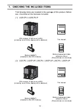
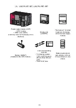
Page 33: ...26CPU P CPU module END cover L6EC A dummy cover for the display unit is attached This manual Battery Q6BAT Installed in the CPU module Battery replacement date stickers to fill out Three stickers on one sheet CPU module END cover L6EC A dummy cover for the display unit is attached This manual Battery Q6BAT Installed in the CPU module Battery replacement date stickers to fill out Three stickers on ...

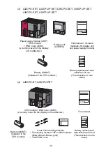
Page 34: ...splay unit and power supply module Battery Q6BAT Installed in the CPU module Battery replacement date stickers to fill out Three stickers on one sheet CPU module END cover L6EC A dummy cover for the display unit is attached This manual Battery Q6BAT Installed in the CPU module A set of terminating resistors Terminating resistor 110 1 2W 2 pieces Brown Brown Brown gold CAUTION note Battery replacem...

Page 35: ... attached Display unit L6DSPU This manual Included materials for display unit and power supply module Battery Q6BAT Installed in the CPU module A set of terminating resistors Terminating resistor 110 1 2W 2 pieces Brown Brown Brown gold CAUTION note Battery replacement date stickers to fill out Three stickers on one sheet ...

Page 36: ...re 25 to 75 C Operating ambient humidity 5 to 95 RH non condensing Storage ambient humidity Vibration resistance Compliant with JIS B 3502 and IEC 61131 2 Frequency Constant acceleration Half amplitude Sweep count Under intermittent vibration 5 to 8 4Hz 3 5mm 10 times each in X Y and Z directions 8 4 to 150Hz 9 8m s2 Under continuous vibration 5 to 8 4Hz 1 75mm 8 4 to 150Hz 4 9m s2 Shock resistanc...

Page 37: ...d from fixed facilities The surge voltage withstand level for up to the rated voltage of 300V is 2500V 3 This index indicates the degree to which conductive material is generated in terms of the environment in which the equipment is used Pollution level 2 is when only non conductive pollution occurs A temporary conductivity caused by condensing must be expected occasionally POINT For the product t...

Page 38: ...shock to the module case or terminal block connector Do not remove a printed circuit board of the module from the case Doing so may cause failure of the module and or printed circuit board When installing the programmable controller in a control panel fully consider its operability maintainability and environmental resistance Securely fix all the MELSEC L series modules used with the DIN rail For ...

Page 39: ...s aspects d opérabilité de maintenabilité et de résistance à l environnement Fixer fermement sur un rail DIN tous les modules de la série MELSEC L à utiliser Pour le détail de l installation voir aussi le Manuel de l utilisateur MELSEC L CPU module conception du matériel maintenance et inspection ...

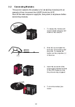
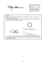
Page 40: ...phases before connecting modules 1 To release the module joint levers located at the top and bottom of the L02CPU 2 Slide the levers toward the front side of the module until they click To release the levers pull the projection 1 of the lever 3 Insert the connector of the power supply module into that of the CPU module so that they are securely engaged 4 To lock the module joint levers Release 1 L...

Page 41: ... joint levers until they click may cause malfunction failure or drop of the module To slide the levers use the projection of the lever Sliding levers with other parts than the projection may cause a difficulty of sliding The metal parts of a module such as the back side may be heated to a high temperature immediately after the power is turned off Therefore be careful not to burn yourself when disc...

Page 42: ...ding to the manual of the DIN rail stopper used 1 Pull down DIN rail hooks on the back of the modules until they click 2 Hang the upper tabs of the modules on a DIN rail and push the modules in position Applicable DIN rail model name IEC 60715 TH35 7 5Fe TH35 7 5Al TH35 15Fe 3 Lock the DIN rail hooks to the DIN rail to secure the modules in the position Pull the hooks up until they click If the ho...

Page 43: ...rding to the arrow on the front of the stopper 6 Hitch the upper hook of the DIN rail stopper to the top of the DIN rail 7 Slide the DIN rail stopper to the leftmost module 8 Hold the DIN rail stopper in the direction opposite to the arrow on the stopper and tighten the screw with a driver Hitch the hook to bottom of the DIN rail Hitch the hook to top of the DIN rail DIN rail stopper DIN rail DIN ...

Page 44: ...ule with the same procedure Install the stopper upside down for the right side POINT Do not slide modules from the edge of the DIN rail when mounting Doing so may damage the metal part located on the back of the module DIN rail stopper DIN rail Right side ...

Page 45: ...6 as well as the Low Voltage Directive since 1997 Manufacturers who recognize their products are compliant to the EMC and Low Voltage Directives are required to attach a CE mark on their products 1 Sales representative in EU member states Authorized representative in Europe is shown below Name MITSUBISHI ELECTRIC EUROPE B V Address Mitsubishi Electric Platz 1 40882 Ratingen Germany ...

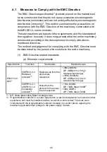
Page 46: ... Directive must be determined by the person who constructs the entire machinery 1 EMC Directive related standards a Emission requirements 1 QP Quasi peak value Mean Average value 2 Programmable controller is an open type device a device designed to be housed in other equipment and must be installed inside a conductive control panel The tests were conducted with the programmable controller installe...

Page 47: ...rst immunity 1 Immunity test in which burst noise is applied to the power line and signal line AC DC main power I O power AC I O unshielded 2kV DC I O analog communication 1kV EN61000 4 5 Surge immunity 1 Immunity test in which lightning surge is applied to the power line and signal line AC power line AC I O power AC I O unshielded 2kV CM 1kV DM DC power line DC I O power 0 5kV CM DM DC I O AC I O...

Page 48: ...vering the bolts so that conductivity can be ensured in the largest possible area Ground the control panel with a thick ground cable so that low impedance can be ensured even at high frequencies Holes in the control panel must be 10cm diameter or less If the holes are larger than 10cm radio wave may be emitted In addition because radio waves leak through a clearance between the control panel and i...

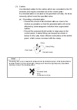
Page 49: ... affected by electromagnetic induction from ungrounded cables Ground the exposed shield section to large area on the control panel A clamp fitting can be used as shown in below In this case mask off inner wall surface of the control panel which comes in contact with the clamp POINT Grounding with a vinyl coated wire soldered onto the shielded section of the shielded cable as shown below is not rec...

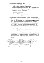
Page 50: ... stations The CC Link Ver 1 10 compatible cable is a shielded cable Strip a part of the jacket as shown below and ground the exposed shield section to the ground as much as possible Always use the specified CC Link Ver 1 10 compatible cable Connect the CC Link module and the CC Link stations to the FG line inside the control panel at the FG terminal as shown below Shielded twisted pair cable Shiel...

Page 51: ...ds of the external wiring cables to the control panel with the AD75CK type cable clamping Mitsubishi Ground the shield section 20 to 30cm away from the module For details of the AD75CK refer to the following AD75CK type Cable Clamping Instruction Manual 20 to 30cm Inside the control panel AD75CK Module ...

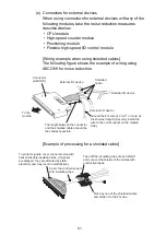
Page 52: ...of 2 mm2 or more at the shortest length Securely install the wire to the control panel on the module side Shielded cable Connector A6CON1 To the module The length between the connector and the shielded cables should be the shortest possible External I O device External I O device Cover the conductive part with insulating tape Pick any one of the shielded cables and solder it to the FG wire Take of...

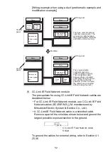
Page 53: ...he cables for external wiring refer to Section 4 1 3 d Relay Relay Relay Programmable controller Relay Relay Relay Modified Wiring duct Wiring duct Control panel Control panel Drive unit Drive unit Noise source Power system etc The drive units are placed near the noise source The connection cable between the programmable controller and drive units is too long Noise source Power system etc Drive un...

Page 54: ...th of the power cable connected to the external power supply terminal to 30m or less Analog digital converter module Digital analog converter module Analog input output module High speed counter module Positioning module Temperature control module Flexible high speed I O control module 4 External power supply Use a CE marked external power supply with a reinforced insulation or a double insulation...

Page 55: ...p the length of cables connected to external devices to 30m or less 10 Positioning module Install the DC power in the same control panel with the modules 11 Temperature control module Install the DC power in the same control panel with the modules 12 Flexible high speed I O control module Take following measures Attach a ferrite core to the cable for the DC power connected to the flexible high spe...

Page 56: ...module is used in Zone A defined in EN61131 2 Keep the length of signal cables connected to the analog input terminals of the following modules to 30m or less Wire cables connected to the external power supply and module power supply terminal in the control panel where the module is installed AJ65BT 64RD3 AJ65BT 64RD4 AJ65BT 68TD For the cable connected to the power supply terminal of the AJ65SBT ...

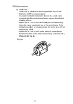
Page 57: ...d by Mitsubishi NEC TOKIN Corporation ESD SR 250 14 CC Link LT module Use the module under the installation environment of Zone A 1 For the specified Zones of the following products refer to the manual provided with each product To supply the CL2DA2 B and CL2AD4 B with power using the CL1PAD1 keep the length of the power cable connected from the CL1PAD1 to the external power supply to 30m or less ...

Page 58: ...ontrol panel does not provide sufficient shielding effects Install a ferrite core to the cable in the position immediately before the cable is extended out of the control panel If the installation position is not appropriate the ferrite core will not produce any effect Install a ferrite core to each power cable as shown below Ferrite core used for the tests conducted by Mitsubishi NEC TOKIN ESD SR...

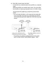
Page 59: ...ables on the input side and output side of the noise filter If bundled the output side noise will be induced into the input side cables from which the noise was filtered Ground the noise filter grounding terminal to the control panel with the shortest cable possible approx 10cm Filter Induction Filter Input side power supply side Input side power supply side Noise will be induced when the input an...

Page 60: ...d on the requirements and standards of the regulation however it does not guarantee that the entire machinery manufactured based on the descriptions complies with the Low Voltage Directive The method and judgment for the Low Voltage Directive must be left at manufacturer s own discretion 1 Standard applied to MELSEC L series modules EN61010 1 Safety of equipment used in measurements controls or la...

Page 61: ...lly between the primary and secondary circuits The I O modules of 24VDC or less rating are out of the Low Voltage Directive application range c GOT Use a CE marked product d Products not subject to the Low Voltage Directive Using 5VDC circuit inside the following modules are out of the Low Voltage Directive application range CPU module including built in I O part SD memory card Display unit RS 232...

Page 62: ...tproof and waterproof features lower the dielectric withstand voltage resulting in insulation destruction The insulation in our programmable controllers are designed to cope with the pollution level 2 so use it in an environment with pollution level 2 or below The pollution level 2 environments can be achieved when the programmable controller is stored in a control panel equivalent to IP54 5 Exter...

Page 63: ...n The reinforced insulation covers the withstand voltages shown below Rated voltage of hazardous voltage area Surge withstand voltage 1 2 50µs 150VAC or lower 2500V 300VAC or lower 4000V Installation Category II source IEC 664 ...

Page 64: ...pecially in the case of DC Also an abnormal operation may occur if an external power supply or the programmable controller fails From the point of view of fail safe circuit and to prevent any of these abnormal operations from leading to the entire system failure configure external fail safe circuits an emergency stop circuit protection circuit and interlock circuit in the areas where incorrect ope...

Page 65: ... DC power establishes the rated voltage Start Stop circuit The stop switch turns off by an emergency stop or a stop caused by exceeding a limit value Interlock circuits Trans former Trans former Fuse Fuse Fuse CPU module DC power Set a period of time for DC power to establish the rated voltage Use of the voltage relay is recommended Low battery alarm lamp or buzzer This relay turns on when the CPU...

Page 66: ...ogrammable controller 2 Set the CPU module to RUN 3 RA2 turns on when DC power is on 4 Timer TM turns on when DC power establishes the rated voltage The timer value is the period of time from when RA2 turns on to when DC power establishes the rated voltage Set this value to 0 5 seconds 5 Turn on the start switch 6 When the electromagnetic contactor MC turns on the output devices will be activated ...

Page 67: ... CPU module DC power Set time for DC power supply to be established Voltage relay is recommended Low battery alarm Lamp or buzzer ON when run by SM403 The stop switch turns off by an emergency stop a stop caused by exceeding a limit value or turning off the ERR contact START SW STOP SW Program Output module ERR RA3 END cover with ERR terminal Output module Provide external interlock circuits for c...

Page 68: ...under strict quality control it is recommended to configure external fail safe circuits to prevent mechanical damage or accidents due to failure of the programmable controller 1 Power on the programmable controller 2 Set the CPU module to RUN 3 RA2 turns on when DC power is on 4 Timer TM turns on when DC power establishes the rated voltage The timer value is the period of time from when RA2 turns ...

Page 69: ...gram for the CPU module and the signal names of the connector refer to the following Pour le câblage du module CPU avec les noms de signaux correspondants voir ci après L02SCPU L02CPU L06CPU L26CPU L26CPU BT B20 B19 B18 B17 B16 B15 B14 B13 B12 B11 B10 B09 B08 B07 B06 B05 B04 B03 B02 B01 A20 A19 A18 A17 A16 A15 A14 A13 A12 A11 A10 A09 A08 A07 A06 A05 A04 A03 A02 A01 ...

Page 70: ...8 IN9 B08 A08 INA INB B07 A07 INC IND B06 A06 INE INF B05 A05 OUT0 OUT1 B04 A04 OUT2 OUT3 B03 A03 OUT4 OUT5 B02 A02 OUT6 OUT7 B01 A01 OUTCOM OUTCOM Output common Input Coincidence output No 2 signal EQU 2 Coincidence output No 1 signal EQU 1 24V PULSE Z 24V CW PULSE Phase A PULSE F CCW SIGN Phase B PULSE R 1 Deviation counter clear signal CLEAR Zero signal PG0 Input common Latch counter input sign...

Page 71: ...uillage Load Charge Lower limit signal Signal de limite basse Near point watchdog signal Signal de surveillance d approche Output Sortie Output common Commun pour sortie Phase Phase Pin No Broche N Positioning function 1 Axis 1 or 2 Axis 2 is in Fonction de positionnement 1 axe 1 ou 2 axe 2 comme indiqué en Row Rangée Signal name Nom de signal Upper limit signal Signal de limite haute Zero signal ...

Page 72: ...dence output No 1 signal EQU 1 24V PULSE Z 24V CW PULSE Phase A PULSE F CCW SIGN Phase B PULSE R 1 Deviation counter clear signal CLEAR Zero signal PG0 Input common Latch counter input signal LATCH Out put Output common Input common Upper limit signal FLS External command signal CHG Drive unit ready signal READY Near point watchdog signal DOG 24V PULSE A 24V Differential PULSE A DIFF COM PULSE A C...

Page 73: ...nd Pulse catch functions Entrée sortie universelle interruption et fonctions à signaux impulsionnels High speed counter function 1 CH1 or 2 CH2 is in Fonction de comptage haute vitesse 1 CH1 ou 2 CH2 comme indiqué en Input Entrée Input common Commun pour entrée Latch counter input signal Signal d entrée compteur de verrouillage Load Charge Lower limit signal Signal de limite basse Near point watch...

Page 74: ...escrits English French English French Pin No Broche N Signal name Nom de signal Mitsubishi 40 pin connector Connecteur 40 broches Mitsubishi Wire Fil Model Modèle Tightening torque Couple de serrage Diameter Diamètre Type Type Material Matériau Temperature rating Gamme de température A6CON1 0 20 to 0 29N m 0 20 à 0 29 N m 22AWG Stranded Torsadé Copper Cuivre 75 C or more 75 C ou plus A6CON2 28 to ...

Page 75: ... l outil recommandé par le fabricant de ces bornes En outre il ne faut pas utiliser de bornes sans soudure sous manchon English French English French Blue bleu CC Link Ver 1 10 compatible cable Câble compatibles CC Link Ver 1 10 Local module Module local Remote module Module distant Master module Module maître Terminating resistor Résistance d extrémité White blanc Yellow jaune Solderless terminal...

Page 76: ...75 Memo ...

Page 77: ...been avoided if functions or structures judged as necessary in the legal safety measures the user s device is subject to or as necessary by industry standards had been provided 4 Failure that could have been avoided if consumable parts battery backlight fuse etc designated in the instruction manual had been correctly serviced or replaced 5 Failure caused by external irresistible forces such as fir...

Page 78: ...IB NA 0800456 I The description of L02SCPU and L26CPU is added January 2013 IB NA 0800456 J The description of L06CPU is added April 2013 IB NA 0800456 K The description of L02SCPU P L06CPU P and L26CPU P is added May 2014 IB NA 0800456 L Addition of descriptions of cUL May 2015 IB NA 0800456 M The description of NZ1MEM GBSD is added October 2015 IB NA 0800456 N Addition of descriptions of measure...

Page 79: ......
Page 80: ...91 20 2710 2000 USA MITSUBISHI ELECTRIC AUTOMATION INC 500 Corporate Woods Parkway Vernon Hills IL 60061 U S A Tel 1 847 478 2100 Turkey Sales office Tel Country Region Sales office Tel Country Region Mexico MITSUBISHI ELECTRIC AUTOMATION INC Mexico Branch Mariano Escobedo 69 Col Zona Industrial Tlalnepantla Edo Mexico C P 54030 Tel 52 55 3067 7500 UAE Brazil MITSUBISHI ELECTRIC DO BRASIL COMÉRCIO...

Reviews: