51
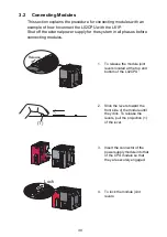
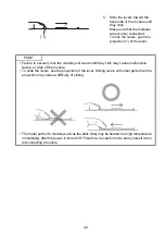
(e) Connectors for external devices
When using connectors for external devices with any of the
following modules, take the noise reduction measures
described below.
• CPU module
• High-speed counter module
• Positioning module
• Flexible high-speed I/O control module
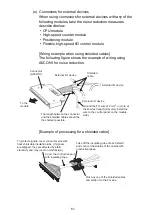
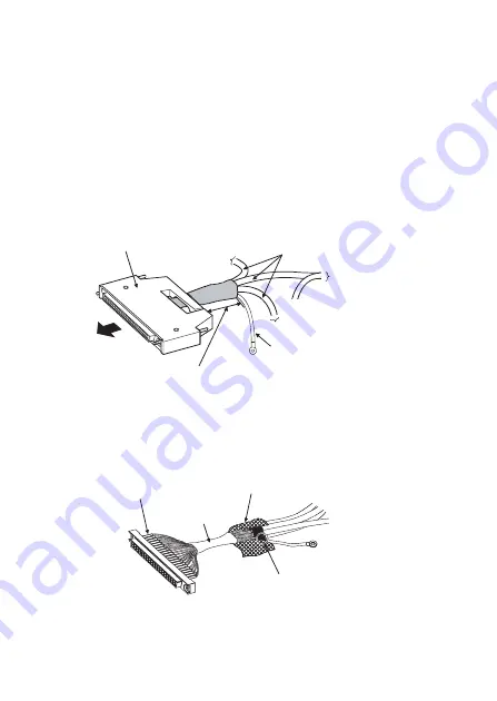
[Wiring example when using shielded cables]
The following figure shows the example of wiring using
A6CON1 for noise reduction.
[Example of processing for a shielded cable]
External I/O device
Ground the FG wire of 2 mm
2
or more at
the shortest length. (Securely install the
wire to the control panel on the module
side.)
Shielded
cable
Connector
(A6CON1)
To the
module
The length between the connector
and the shielded cables should be
the shortest possible.
External I/O device
External I/O device
Cover the conductive part
with insulating tape.
Pick any one of the shielded cables
and solder it to the FG wire.
Take off the insulating tube of each shield
and connect the shields of the cables with
conductive tapes.
To protect signals, cover connector pins with
heat shrinkable insulation tube. (If signals
are stripped, they are affected by static
electricity and may result in malfunction.)
Summary of Contents for 13J240
Page 76: ...75 Memo ...
Page 79: ......


