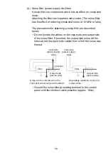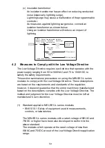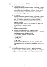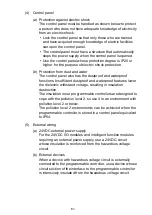
64
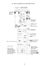
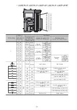
(1) System design circuit example
(a) When not using END cover with ERR terminal
MC
RA1
RA2
XM
Ym
Yn
MC2
MC1
M10
NO
MC MC
SM52
SM52
SM403
SM403
XM
TM
MC
MC2
MC1
Ym
Yn
MC
RA1
MC
MC
RA2
L
MC1
RA1
MC2
Ym
TM
MC1 NO M10
MC1
MC2
L
RA1
MC
Ym
Yn
(-) (+)
Yn
For AC power
For AC and DC power
Power
supply
Power
supply
Transformer
Fuse
CPU module
Start
switch
Stop
switch
Input
module
Output module
Output module
Low battery alarm
(lamp or buzzer)
This relay turns on
when the CPU module
starts running by SM403.
Power to the output
devices is shut off
when the stop switch
turns off.
The circuit is
interlocked with
RA1
(run monitor relay).
Signals are input
when DC power
establishes
the rated voltage.
Start/Stop circuit
The stop switch turns off
by an emergency stop
or a stop caused by
exceeding a limit value.
Interlock circuits
Trans-
former
Trans-
former
Fuse
Fuse
Fuse
CPU module
DC
power
Set a period of time for
DC power to establish
the rated voltage.
Use of the voltage
relay is recommended.
Low battery alarm
(lamp or buzzer)
This relay turns on
when the CPU module
starts running by SM403
Power to the output
devices is shut off
when the stop switch
turns off.
The stop switch turns
off by an emergency stop
or a stop caused by
exceeding a limit value.
START
SW
STOP
SW
Program
Program
Output module
Output module
Externally configure
interlock circuits for
conflicting operations,
such as forward/reverse
rotations, and for parts
where abnormal operation
may result in mechanical
damage or accidents.
Summary of Contents for 13J240
Page 76: ...75 Memo ...
Page 79: ......


