background image

10

5.7. Precautions when reusing existing R22 refrigerant pipes

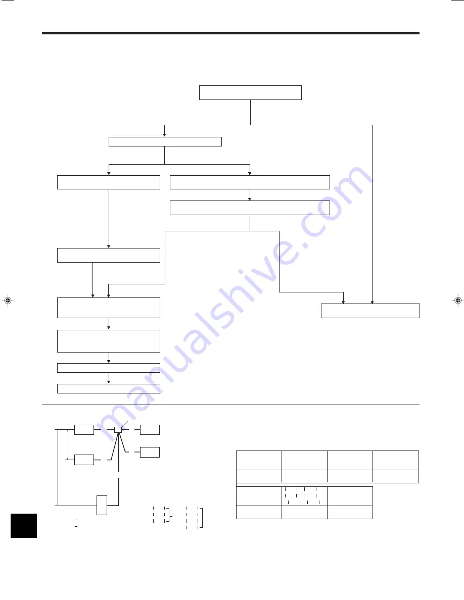
• Refer to the flowchart below to determine if the existing pipes can be used.
• See below for oil condition.

Clear to slight yellow color 

 Normal

Black or brown 

 Pipe cleaning is necessary.

• If the diameter of the existing pipes is different from the specified diameter, refer to technological data materials to confirm if the pipes can be used.
• Additional charge amount for 70 m.

Measure the existing pipe thickness and check
for damage.

The existing pipe thickness meets specifi-
cations and the pipes are not damaged.

The existing pipe thickness does not meet
specifications or the pipes are damaged.

Check if the existing air conditioner can operate.

The existing air conditioner can operate.

The existing air conditioner cannot operate.

After operating the cooling system for about
30 minutes, do a pump down work.

Use a refrigerant collecting device to collect the refrigerant.

Check the oil condition when collecting the refrigerant.

Oil is clean. (Clear to brownish color)

Oil is dirty. (Black color)

When the compressor bearings are
glazed, rotation scratches are present,
or the compressor breaks down, iron
particles or oil deterioration will blacken
the oil.

Disconnect the existing air conditioner from
the pipes.

The existing piping can be reused.
After flaring the pipes again, connect the
new air conditioner.

The existing pipes cannot be reused.
Use new pipes.

5. Installing the refrigerant piping

5.8. For twin/triple/quadruple combination (Fig. 5-8)

• When this unit is used as a FREE COMPO MULTI unit, install the refrigerant piping

with the restrictions indicated in the drawing on the left. In addition, if the restric-
tions are going to be exceeded, or if there are going to be combinations of indoor
and outdoor units, refer to installation instructions for the indoor unit for details
about the installation.

 B–C 

 B–D 

 8 m

 C–D 

• A+B+C(+D) 

 120 m * “D” is for triple.

• A+B+C(+E) 

 120 m * “E” is for four (quadruple).

Fig. 5-8

Perform the following inspections: air
tightness test, vacuum dryness (additional
refrigerant charge), gas leakage check

Replacement operation

Test operation

* Refer to 12 page

Permissible total

A+B or A+C

Charge-less

Outdoor unit

 piping length

or

piping length

A+B+C+D+E

A+D or A+E

A+B+C+D+E

RP200

120 m and less

100 m and less

30 m and less

RP250

 B-C  or  B-D  or

Outdoor unit

 B-E  or  C-D  or

No. of bends

 C-E  or  D-E 

RP200

8 m  and less

Within 15

RP250

A

Indoor unit

B

Outdoor unit

C

Multi distribution pipe (option)

D

Height difference (Indoor unit-
Outdoor unit) Max. 40 m

E

Height difference (Indoor unit-
Indoor unit) Max. 1 m

A: Main piping

B, C, D, E: Branch piping

<Limits of refrigerant piping installation>

A

A

A

A

C

E

D

D

E

B

C

A

B

 A+B 

 A+C 

Max. 100 m

 A+D 

 A+E 

Summary of Contents for 250 YHA-A

Page 1: ...English INSTALLATION MANUAL For safe and correct use please read this installation manual thoroughly before installing the air conditioner unit Air Conditioners PUHZ RP200 250 YHA A FOR INSTALLER ...

Page 2: ... it with any other refrig erant and do not allow air to remain in the lines Air enclosed in the lines can cause pressure peaks resulting in a rupture and other hazards Use only accessories authorized by Mitsubishi Electric and ask a dealer or an authorized technician to install them If accessories are incorrectly in stalled water leakage electric shock or fire may result Do not alter the unit Cons...

Page 3: ... in the refrigeration oil oil deterioration may result Do not use refrigerant other than R410A refrigerant If another refrigerant is used the chlorine will cause the oil to deteriorate Use the following tools specifically designed for use with R410A refrigerant The following tools are necessary to use R410A refrigerant Contact your nearest dealer for any questions Tools for R410A Gauge manifold Fl...

Page 4: ...e overall height of the unit add the dimen sion shown as h in the drawing on the left to L1 and L2 on Table 2 Table 2 mm L1 L2 450 100 2 4 2 When installing multiple outdoor units Fig 2 8 When installing multiple units make sure to take into consideration factors such as providing enough space for people to pass through ample space between blocks of units and sufficient space for air flow as shown...

Page 5: ...openings at the base of the unit Note 1 Always use care when transporting a unit by forklift on rainy days as slip page can occur 2 Never use dangerous sudden movements such as accelerating or applying the brakes suddenly or turning the steering wheel quickly when transporting the unit by forklift 3 2 Transporting by pallet truck Fig 3 2 When using a pallet truck to transport the unit insert the f...

Page 6: ... stalled has sufficient strength If the surface is not strong enough the unit could fall over and cause damage or injury Make sure that the unit is installed so that it will be able to withstand earth quakes and strong winds Damage or injury could occur if the unit tips over due to an earthquake or strong wind Be sure to install the unit in a sturdy level surface to prevent rattling noises during ...

Page 7: ...ne foam insu lation materials specific gravity of 0 03 thickness of 9 mm or more Apply thin layer of refrigerant oil to pipe and joint seating surface before tightening flare nut A Use two wrenches to tighten piping connections B Use leak detector or soapy water to check for gas leaks after connections are com pleted Apply refrigerating machine oil over the entire flare seat surface C Do not apply...

Page 8: ...air from the refrigerant lines After the valve work is completed tighten the valve caps to the correct torque Valve size Tightening torque N m kgf cm Valve cap Service port cap 3 8 ø9 52 22 28 220 280 12 16 1 2 ø12 7 25 31 250 310 120 160 1 ø25 4 36 44 360 440 11 5 13 9 115 139 Failure to replace and tighten the caps may result in refrigerant leakage In addition do not damage the insides of the va...

Page 9: ... less 41 50 m and less 51 60 m and less 61 70 m and less 71 120 m and less 0 9 kg 1 8 kg 2 7 kg 3 6 kg 1 2 kg 2 4 kg 3 6 kg 4 8 kg Outdoor unit RP200 RP250 At time of shipping kg 10 5 10 5 No additional charge necessary Calculate the amount of additional refrigerant charge using formula provided below Main piping Liquid line size ø9 52 overall length 0 09 Gasline ø28 58 m 0 09 kg m Branch piping L...

Page 10: ...ner from the pipes The existing piping can be reused After flaring the pipes again connect the new air conditioner The existing pipes cannot be reused Use new pipes 5 Installing the refrigerant piping 5 8 For twin triple quadruple combination Fig 5 8 When this unit is used as a FREE COMPO MULTI unit install the refrigerant piping with the restrictions indicated in the drawing on the left In additi...

Page 11: ...ting cords shall not be lighter than polychloroprene sheathed flexible cord Design 245 IEC 57 3 Use an earth wire which is longer than the other cords so that it will not become disconnected when tension is applied The earth wire should also be thicker than the power supply cord so that it can stand any surge of electricity when trouble occurs 7 2 Field electrical wiring If the wiring connecting t...

Page 12: ...ended period the insulation resistance will drop below 1 MΩ due to refrigerant accumulat ing in the compressor This is not a malfunction Perform the following procedures 1 Remove the wires from the compressor and measure the insulation resistance of the compressor 2 If the insulation resistance is below 1 MΩ the compressor is faulty or the resist ance dropped due the accumulation of refrigerant in...

Page 13: ...W4 2 ON After performing the test run set SW4 1 to OFF After power is supplied a small clicking noise may be heard from the inside of the outdoor unit The electronic expansion valve is opening and closing The unit is not faulty A few seconds after the compressor starts a clanging noise may be heard from the inside of the outdoor unit The noise is coming from the check valve due to the small differ...

Page 14: ...ltaneous twin Refrigerant address 01 G Simultaneous triple Refrigerant address 02 ON OFF 3 4 5 6 E SW 1 3 6 ON OFF 3 4 5 6 F SW 1 3 6 ON OFF 3 4 5 6 G SW 1 3 6 Operation according to switch setting ON OFF Start Normal Clear Normal Settings for outdoor unit ad dresses 0 to 15 SW1 Function table SW1 Function 1 Compulsory de frosting 2 Error history clear 3 4 5 6 ON 1 2 3 4 5 6 OFF TB4 TB5 TB1 TB4 TB...

Page 15: ......

Page 16: ...ase be sure to put the contact address telephone number on this manual before handing it to the customer HEAD OFFICE TOKYO BLDG 2 7 3 MARUNOUCHI CHIYODA KU TOKYO 100 8310 JAPAN Printed in Japan BG79U638H03 ...

Reviews: