background image


Mitsubishi Electric Industrial Robots 


CR800/750/700/500 series 


RT ToolBox3 / RT ToolBox3 mini 


User's Manual 

(3F-14C-WINE/3F-15C-WINE) 


BFP-A3495-J


Summary of Contents for 3F-14C-WINE

Page 1: ...Mitsubishi Electric Industrial Robots CR800 750 700 500 series RT ToolBox3 RT ToolBox3 mini User s Manual 3F 14C WINE 3F 15C WINE BFP A3495 J ...

Page 2: ...ch setting During teaching work label the start switch etc to indicate that teaching work is underway The same is true for any maintenance work done with the power source not cut off Display that teaching work is underway During operation prevent contact between workers and robots by preparing a fence and a barrier Setting up a safety fence Determine a uniform signal to relevant staff for the star...

Page 3: ...rsonal injury or damage Ground the robot and controller reliably Failure to do this can cause malfunction due to noise or in an extreme case electrical shock Display the operating state while the robot is operating Lack of such a display can result in someone coming too close to the robot by mistake or mistaken operation Always secure the priority rights for control of the robot before doing any t...

Page 4: ...program parameters or other internal information within the robot s controller do not switch the robot controller s main power supply OFF If the robot controller s main power supply is switched OFF during automatic operation or while a program or parameter is being written there is a danger of the internal information in the robot controller being corrupted For using RH 5AH 10AH 15AH series or RH ...

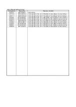
Page 5: ...ware revision history 2018 08 BFP A3495 D Corresponds to the Ver 1 30G Refer to the software revision history 2018 12 BFP A3495 E Corresponds to the Ver 1 32J Refer to the software revision history 2019 03 BFP A3495 F Corresponds to the Ver 1 40S Refer to the software revision history 2019 04 BFP A3495 G Corresponds to the Ver 1 50C Refer to the software revision history 2020 01 BFP A3495 H Corres...

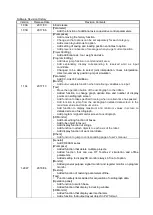
Page 6: ...h screen Add function to take specified time log when a certain time has passed Add function to jump from the oscillograph detailed data screen to the maximum value and minimum value Add function to display maximum and minimum values in screen to detailed screen of oscillograph Add program signal monitor screen to oscillograph 3D Monitor Add bulk editing function of boxes Add tube object to layout...

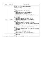
Page 7: ...ng Added function that convert blank lines to comments Added function that save program in form of no number Setting Origin Data Added detailed work procedure 3D Monitor Added function that can set TCP hand tip at hand editing Added function to write TCP hand selection to tool parameter from hand property Added function that plane can also be output when layout objects are output in PLY format Add...

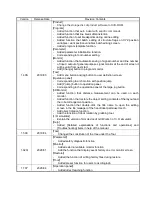
Page 8: ...n to operation panel Corresponding to the operation panel of the large jog button 3D Monitor Added function that distance measurement can be used on each monitor Added function that restore the object setting contents of the layout and the robot arrangement position Added function that double click the title name to open the editing screen in the file manager of the hand robot parts user mech Add ...

Page 9: ...esent a danger of injury It could also present a danger of just physical damage This document uses the following general terms and abbreviations General Term Abbreviation Contents RCPU General term for Mitsubishi PLC CPU modules of R04CPU R04ENCPU R08CPU R08ENCPU R16CPU R16ENCPU R32CPU R32ENCPU R120CPU R120ENCPU R08PCPU R16PCPU R32PCPU R120PCPU R08SFCPU R16SFCPU R32SFCPU and R120SFCPU Universal mo...

Page 10: ... Using the Ribbon 2 41 2 3 Linking Between the Offline and Simulation Environments 2 41 2 4 Support of Program Language MELFA BASIC VI 2 42 2 5 Discontinuation of Robot Individual Display in 3D Monitor 2 42 2 6 Memory of screen display position and size 2 42 3 RT ToolBox3 Usage 3 44 3 1 Starting RT ToolBox3 3 44 3 2 Explanation of RT ToolBox3 Screens 3 45 3 3 Changes in RT ToolBox3 Display Format ...

Page 11: ... after adding the project 8 85 8 12 Editing Projects 8 86 8 13 Deleting a Project 8 87 8 14 Contents of Project Tree 8 88 8 15 Copying Programs Between Projects 8 89 8 16 Importing projects 8 90 8 17 Option Setting 8 91 8 18 Offline Online Simulation 8 92 9 Connecting to the Robot 9 94 9 1 Robots Connected and Types of Communication 9 94 9 2 Connection Settings 9 96 9 2 1 USB Communication Setting...

Page 12: ... 4 Save as template 11 168 11 9 5 Items written when saving in robot 11 169 11 10 Program Printing 11 171 11 10 1 Checking a print image 11 171 11 10 2 Printing a program 11 171 11 10 3 Program print settings 11 171 11 11 Program Debugging 11 174 11 11 1 Starting debugging 11 174 11 11 2 Executing programs step by step 11 176 11 11 3 Revising programs 11 176 11 11 4 Setting and deleting breakpoint...

Page 13: ...up operation parameters 13 229 13 3 12 Movement parameters 13 230 13 3 13 Work coordinate paramaters 13 231 13 3 14 Force control parameters 13 232 13 3 15 Collision avoidance parameters 13 235 13 3 16 Safety Parameters CR750 CR700 13 238 13 4 Program Parameters 13 242 13 4 1 Slot table parameters 13 242 13 4 2 Program language parameters 13 243 13 4 3 Command parameters 13 243 13 4 4 User error p...

Page 14: ...14 3 7 Device Monitor 14 315 14 4 Operation Monitoring 14 317 14 4 1 Operating Information 14 317 14 4 2 Production Information 14 317 14 5 Servo Monitor 14 318 14 5 1 Position ABS 14 319 14 5 2 Speed 14 320 14 5 3 Current 14 321 14 5 4 Load 14 322 14 5 5 Power 14 323 15 Maintenance 15 324 15 1 Setting Origin Data 15 324 15 1 1 Origin data input 15 326 15 1 2 Mechanical stopper 15 328 15 1 3 Tool ...

Page 15: ...project PC 17 383 17 4 Offline restore PC Offline project 17 384 17 5 Property Display of Backup Data 17 385 17 6 Deleting Backup Data 17 386 17 7 Open Backup program 17 386 17 8 Check Backup programs 17 387 17 9 Open the event history from backup data 17 387 17 10 Open the error history form backup data 17 387 17 11 Open the error record form backup data 17 388 18 Tool functions 18 389 18 1 Oscil...

Page 16: ... the Operation Panel 19 467 19 1 1 Starting the operation panel 19 467 19 1 2 Operation panel commands on the ribbon 19 470 19 2 Functions of Operation Panel 19 471 19 2 1 Jog operation 19 471 19 2 2 Program execution 19 476 19 2 3 Specifying the starting line for program execution 19 476 19 2 4 Step operation 19 477 19 2 5 Direct execution 19 478 19 3 Change to the small operation panel 19 479 19...

Page 17: ... Settings 21 552 21 7 1 Hand display content 21 552 21 7 2 Display conditions 21 553 21 7 3 Write TCP hand tip 21 555 21 8 Robot Parts Display Settings 21 555 21 8 1 Robot parts display content 21 555 21 8 2 Display conditions 21 556 21 9 User Mech Display Settings 21 557 21 9 1 Display contents of user mechanism 21 558 21 9 2 User mech type and relationship to robot 21 560 21 9 3 User mech lnterf...

Page 18: ...r 23 613 23 1 Summary 23 613 23 2 Simulator settings 23 613 23 3 Signal connection edit screen 23 615 23 4 Starting I O Simulator 23 619 23 5 I O Simulator Connection Status 23 621 23 6 Stopping I O simulator 23 621 24 Document out 24 622 24 1 Start up of the document creation screen 24 622 24 2 Selection of content to be output to document 24 623 24 3 Save document 24 625 25 MELFA Works 25 626 26...

Page 19: ...ure Product ID is printed on it Please contact the branch office or the agency if there is some shortage in the package 1 2 2 Checking the DVD ROM contents The DVD ROM has the following configuration 1 2 3 About the MelfaRXM ocx communications middleware MelfaRXM ocx is the ActiveX control that communicates with the robot controller You can create the Windows Application of MELFA ROBOT by using th...

Page 20: ...2D 232CBL03M Mitsubishi Electric CRn 500 series RS MAXY CBL RS AT RCBL for expansion serial interface option Mitsubishi Electric For expansion option box CR1 EB3 RS AT RCBL Mitsubishi Electric Table 1 2 CR800 R CR800 Q CR750 Q CRnQ 700 Series Communication Cables Method Description Cables confirmed by Mitsubishi Electric to operate properly Model name Manufacturer USB USB A type to mini B type ZUM...

Page 21: ...32 Only CRnD 700 series GOT communications Communicate with CR800 D CR750 D CRnD 700 series controller connected with the GOT via Ethernet by USB RS 232 GOT 2000 1000 series and the Ethernet communication unit GT25 J71E71 100 GT15 J1E71 100 are needed CR800 R CR800 Q CR750 Q CRnQ 700 series The photo is the robot controller for CR800 R CRnQ_R communications USB 2 Ethernet TCP IP The PLC RCPU Ether...

Page 22: ...operate on Windows Communications functions Communications port USB2 0 Note This cannot be used for connection with the CRn 500 series as there is no USB LAN 100Base TX 10Base T RS 232 communication port that operates on Windows Minimum 9600bps 1 port Must have one of the above interfaces OSs for which operation is warranted Windows XP 32 bit version Windows Vista 32 bit version Windows 7 Starter ...

Page 23: ...select Run When installing log in as a user with administrator rights When installing log in as a user with administrator rights The system will not let you install if you log in as a user who does not have administrator rights Please input the product ID attached to RT ToolBox3 again when you install the standard version of RT ToolBox3 in the personal computer in which iQ Works MELSOFT Navigator ...

Page 24: ...ead of executing the Run command The Product ID is printed on the License Certificate After the installation is completed the computer may need to be rebooted Start f Input Product ID i Start the program and confirm whether the product was installed correctly h Installation Wizard Complete Finish a Set the DVD ROM in PC s DVD ROM drive b Open Setup exe in DVD ROM If it does not start automatically...

Page 25: ...n and warning message displayed during installation During installation on Windows XP or Windows Vista the following confirmation and warning messages are displayed Select to continue installation If you choose not to install please execute the installation again Installation confirmation message for USB driver software for Windows Vista When Always trust software from MITSUBISHI ELECTRIC CORPORAT...

Page 26: ...ersion 3 5 includes NET 2 0 and 3 0 feature as follows 1 Be ready to connect the PC to the Internet 2 Select Programs Turn Windows features on or off from the Control Panel 3 Check the NET Framework 3 5 includes NET 2 0 and 3 0 check box on the Turn Windows features on or off screen and click OK ...

Page 27: ...1 27 1 27 4 Select Download files from Windows Update when the following screen is shown 5 This process is complete when the following screen is shown ...

Page 28: ...stallation Windows 7 Execute Start Program Functions or Uninstall Program select the application name then execute the uninstallation Windows 8 8 1 10 Press the Windows X key and select the Program Functions from the displayed menu With Program Functions select the application name then execute the uninstallation Start uninstallation From Start Control Panel display the control panel and select Ad...

Page 29: ... cable the screen on the left is displayed Select Install the software automatically Recommended then click the Next button Installation of the USB driver starts 2 When the screen on the left is displayed the installation is complete Click the Finish button to end the installation Completed 1 5 3 2 When using Windows Vista When you connect the CR800 D CR750 D CRnD 700 robot controller and the comp...

Page 30: ... recommend changing to LAN communication If you cannot communicate with the CR800 D series robot controller with USB in Windows 7 64 bit version Please perform Windows Update and update Windows to the latest state When communicating with the robot controller of the CR800 D series with USB in Windows 7 64 bit version Application of Security Update for Windows 7 for x64 based Systems KB3033929 is ma...

Page 31: ...versal model QCPU by a USB cable Choose Yes now and every time I connect a device and click the Next button 2 The screen on the left appears Choose Install from a list or specific location Advanced and click the Next button If the USB driver cannot be installed check the following setting When Windows XP is used If you have selected Block Never install unsigned driver software after Control Panel ...

Page 32: ...ers of the first installed product After setting click the Next button 4 The screen on the left appears Click the Continue Anyway button to continue the installation of the USB driver No problem will occur after installation of the USB driver 5 The screen on the left appears to indicate completion of installation Click the Finish button Completed 1 5 4 2 When using Windows Vista The following indi...

Page 33: ...The screen on the left is displayed Select Browse my computer for driver software advanced 3 The screen on the left is displayed Select C Melsec EasySocket USBDrivers If volume MELSOFT products have been installed browse the installation destination EasySocket USBDrivers of the first installed product After setting click the Next button 4 The screen on the left is displayed Select Install this dri...

Page 34: ...hen using Windows 7 8 8 1 10 The following indicates the procedure for installing the USB driver when using Windows 7 8 8 1 10 1 When Control panel is selected from the start menu with the USB cable connected the following screens are displayed The screen on the left is displayed Click the part circled in red in this screen ...

Page 35: ...1 35 1 35 2 The screen on the left is displayed Click the part circled in red in this screen 3 The screen on the left is displayed Click the part circled in red in this screen ...

Page 36: ...displayed Right click on the MELSEC displayed on this screen Select Update Driver Software in the menu displayed upon right clicking this item 5 The screen on the left is displayed Click Browse my computer for driver software on the bottom ...

Page 37: ...roducts have been installed browse the installation destination EasySocket USBDrivers of the first installed product After setting click the Next button 7 The screen on the left is displayed Click install Completed 8 The screen on the left appears indicating completion of installation Click the Finish button ...

Page 38: ...ll by the following procedure 1 5 5 1 When using Windows XP The following indicates the procedure for installing the USB driver when using Windows Professional 1 The screen shown on the left appears when you connect the personal computer and GOT with a USB cable Choose Yes now and every time I connect a device and click the Next button 2 The screen on the left appears Select Install the software a...

Page 39: ...ware Driver Signing the USB driver may not be installed Choose Ignore Install the software anyway and don t ask for my approval or Warn Prompt me each time to choose an action for Driver Signing and install the USB driver 1 5 5 2 When using Windows Vista When you connect the GOT and the computer by the USB cable installation starts and completes automatically 1 5 5 3 When using Windows 7 8 8 1 10 ...

Page 40: ... software RT ToolBox 2 Older version of this software Cannot be used at the same time as this software MELFA Works 3D robot simulator Cannot be used at the same time as this software MELFA Vision Network vision sensor software Start this software first E EN series computer support software for Windows E EN series software Cannot be used at the same time as this software P P 2 R 250R R 300R series ...

Page 41: ...the tool bar and menus that were used in RT ToolBox2 in RT ToolBox3 a ribbon interface is made available that allows the user to quickly find the required commands For an explanation on the ribbon refer to 6 Ribbon 2 3 Linking Between the Offline and Simulation Environments In RT ToolBox2 the environments for offline editing and simulator tasks were independent from each other For this reason prog...

Page 42: ...ox3 the program language MELFA BASIC VI that has been added on CR800 series controllers is now supported For details refer to 10 Robot Programming Language Setting 2 5 Discontinuation of Robot Individual Display in 3D Monitor In the RT ToolBox2 3D monitor displays for individual robots by each project and all robots in workspaces were displayed However in RT ToolBox3 to avoid confusion among users...

Page 43: ...play position and size of each screen Next time the same screen is displayed with the same position and size as the previous time Please be careful if initialized by this method display position and size of all screens are initialized Caution Remember s the display position and size of each screen ...

Page 44: ...ort cut Figure 3 1 RT ToolBox3 Shortcut From Start button All Programs MELSOFT select RT ToolBox3 and start it Figure 3 2 RT ToolBox3 Initial Screen When you start RT ToolBox3 Communication Server 2 is started up as an icon This Communication Server 2 has functions for connecting with a robot controller or during a simulation a virtual controller Do not close Communication Server 2 Figure 3 3 Comm...

Page 45: ...on of the main RT ToolBox3 screen is as follows Figure 3 4 Explanation of Main Screen 1 Title bar 2 Ribbon 3 Project tree 4 Property window The screen currently active is displayed on top 6 Screens 6 Screens 8 Status bar 7 Output window 5 Individual function tree ...

Page 46: ...ze is changed you can close RT ToolBox3 Displays the name of the workspace currently being edited Minimize RT ToolBox3 Maximize Minimize RT ToolBox3 The status of the connection with the robot is displayed The connection statuses are online offline and simulation Click to close RT ToolBox3 Operations assigned to each icon can be performed Save Print Change RT ToolBox3 Mode and others ...

Page 47: ...e docking window refer to 7 Docking Window When the project tree is closed it can be redisplayed by checking Workspace in the View tab View group on the ribbon 4 Property window You can reference various attributes of the workspace being edited If you click an item on the project tree its attributes are displayed The property window is a docking window For details on the docking window refer to 7 ...

Page 48: ...splayed the displayed tree can be switched by selecting the desired tab The window of the individual function tree is a docking window For details on the docking window refer to 7 Docking Window When the individual function tree is closed it can be redisplayed by clicking the Reset the window layout button in the View tab View group on the ribbon ...

Page 49: ...o change the screen size with the button in the upper right of the screen 7 Output window RT ToolBox3 event logs and search results for example are displayed in this window There are two types of output window Output and Search In the Output window event logs such as the content of syntax check errors in program editing are output In the Search window search results in program editing for example ...

Page 50: ...ng Window When an output window is closed the respective output window can be redisplayed by checking Output or Search in the View tab View group on the ribbon 8 Status bar Displays RT ToolBox3 status information 9 Context menu display The context menu can be displayed by clicking the mouse right button This is a handy menu depending on work contents and it improves work efficiency For example Cop...

Page 51: ... follows Languages English 英語 Japanese 日本語 Chinese Simplified 简体中文 Chinese traditional 繁體中文 Version 1 01B or later when non Japan has been selected regardless of the LNG parameter setting the controller turns on the language of communication in English Sets the Japan and switch to Japan This function can be used with Version 1 01B or later of the CR800 750 700 series controller 3 3 2 Changing the ...

Page 52: ...er to 10 Robot Programming Language Setting 3 4 2 Displaying the instruction manual The instruction manuals for the robot controller and RT ToolBox3 can be displayed by selecting from the Help tab Instruction Manual drop down menu on the ribbon Also when the screen or tab is open clicking the button display and jump to the manual page of this screen on the title bar will display the items of the m...

Page 53: ... status of the personal computer items related to the manual may not be displayed The relationship between the software installation status of the personal computer and the display status of the manual is as follows Table 3 1 Display status when displaying the manual from the button software installation status Display state of manual Internet Explorer and Adobe Reader are installed The correspond...

Page 54: ...ectric FA site You can connect to the Mitsubishi Electric FA site by clicking the Help tab Connect to FA Site button on the ribbon To be able to connect to the Mitsubishi Electric FA site your personal computer environment must be able to support an Internet connection 3 4 4 Displaying version information The screen for checking the version and product ID of RT ToolBox3 is displayed by clicking th...

Page 55: ...ished Light blue or Blue Connection wait Indicates that a communication to verify connection is being made in the case of RS 232 connection Indicates the wait status for communication port connection in the case of TCP IP and USB connection Green Connection error Displayed when the data reception enable signal cannot be detected because a cable has been disconnected or the robot has not been start...

Page 56: ...er by higher reliability communication In this case line state color connecting of communication server 2 is Blue Table 3 3 Combination of higher reliability communication Robot controller software version CR800 D R Q CR750 D CRnD 700 CR750 Q CRnQ 700 CRn 500 All versions Ver P8 or later Ver P7a or earlier Ver N8 or later Ver N7 or earlier All versions Combination with this software Conventional c...

Page 57: ...pper right of the screen When you close RT ToolBox3 Communication Server 2 also closes automatically Cautions on higher reliability communication by TCP IP When connected higher reliability TCP IP communication connect only one line per port number If two or more lines are connected to the same port number a communication error may occur Caution ...

Page 58: ...s concerning workspace operation Notes 2 1 The workspace name and the workspace title cannot be changed When RT ToolBox3 is started from iQ Works MELSOFT Navigator the workspace name and the workspace title cannot be changed Edit workspace in the dropdown menu of the workspace name is displayed in the gray and cannot be selected Refer to Figure 4 1 Menu of Workspace and Dropdown menu of the Worksp...

Page 59: ...orkspace name and Delete project in the dropdown menu by selecting a project name are display in the gray and cannot be selected Figure 4 2 Menu of Workspace and Dropdown menu of the Workspace Notes 3 2 It is not possible to change a project name When RT ToolBox3 is started from iQ Works MELSOFT Navigator it is not possible to change the project in the editing workspace Project name in Edit projec...

Page 60: ...d directly by the start menu etc However it becomes impossible to take the correspondence in iQ Works MELSOFT Navigator when these information is changed Please do not change the composition changing a workspace name changing a title adding a project deleting a project or changing a project name of workspace when editing them with RT ToolBox3 started directly Prohibited matter in RT ToolBox3 start...

Page 61: ...unction The parameters can be set individually per robot function The functions are as follows Operating range Jog Hand Weight and size Tool Slot table Output signal reset pattern Dedicated input output signal allocation RS 232 settings User defined area Free plane limit Evacuation point Robot language Added axes Collision detection Heater operation Operation parameters Program parameters User err...

Page 62: ...ce control log data graph in the PC and robot controllers Tool automatic calculation The tool length is calculated automatically and the value of a tool parameter is set up Simulation This can be used in connection with a virtual robot This can only be used in the standard edition Same functions as online The same functions can be used with a virtual robot controller as with an online one Tact tim...

Page 63: ...ttings and operations relating to 3D monitor functions are available For an explanation of 3D monitor functions refer to 21 3D Monitor File This is used for file reading saving and performing other operations in program editing and in the spline editing functions This tab is displayed only when the screen for a related function is active Edit Operation commands for editing file contents are availa...

Page 64: ...6 64 6 64 Help Commands for displaying language help for robot programs and the RT ToolBox3 Instruction Manual are available ...

Page 65: ... editing screen for example can be increased Even with the ribbon minimized ribbon commands can be operated by clicking the tab Figure 6 3 Ribbon in Minimized State The ribbon can be minimized by either of the following operations Select and check Minimize the Ribbon from the menu that is displayed by clicking at the ribbon top Double click one of the tabs To return a minimized ribbon to its origi...

Page 66: ... top or bottom positions 7 1 Moving and Placing Docking Windows A docking window becomes separated from the main screen by dragging the title area of the docking window Docking windows in a separated state can be moved as desired inside and outside RT ToolBox3 Docking windows can also be used as they are in a separated state Figure 7 1 Docking Window in Separated State While a separated docking wi...

Page 67: ...7 67 7 67 The docking window is docked to the position indicated by the arrow by dropping the window over one of the marks Figure 7 3 When a Docking Window Is Docked to the Bottom of the Main Screen ...

Page 68: ...p or bottom of the docked window by dropping the window over one of the marks in this state Figure 7 5 When a Window Is Aligned With the Left Side of the Docked Window Also the window can be placed overlaying a docked window when it is dropped on top of the mark When multiple windows are displayed overlaying each other the currently displayed window contents can be switched by changing the selecte...

Page 69: ...ntents can be temporarily displayed by moving the mouse cursor to the position of the window name in this state A minimized docking window is displayed by a side facing pin Figure 7 7 Minimizing Docking Windows To return a minimized docking window to its original size click the side facing pin 7 4 Resetting a Docking Window to Its Default Layout A docking window can be reset to its default layout ...

Page 70: ... keep the layout of the docking window for each workspace or always open it in the same layout Since the initial value is Workspace you need to select Account to always open in the same layout Option screen is displayed by clicking the Option button in the Workspace drop down menu on the ribbon Figure 7 9 Setting of Screen Layout Mode ...

Page 71: ...n the workspace When using multiple robot controllers it is convenient to manage with separate workspaces for each manufacturing line and installation location 1 Using multiple robot controllers up to 32 Figure 8 1 Using Multiple Robot Controllers 2 Using 1 robot controller Figure 8 2 Using One Robot Controller Workspace Project 1 Communication RT ToolBox3 Workspace Project 1 Project 2 Project 32 ...

Page 72: ...hing offline see 8 18 Offline Online Simulation Caution You cannot edit multiple workspaces at the same time With this software you cannot edit multiple workspaces at the same time Register to a single workspace all the projects controllers you want to reference at the same time Simultaneous connection with 32 units The maximum of 32 robot connections is a theoretical value It does not guarantee t...

Page 73: ... click the OK button You can change the robot model of 3D monitor to a simple model Please refer to 21 13 Types of Robot Model for the content of the simple model Figure 8 3 Creating a New Workspace The project tree is displayed in the workspace and the RC1 project is created as the default value This project name can be changed later For details see 8 12 Editing Projects If you want to display a ...

Page 74: ...ded to the Workspace tab on the ribbon You can open one of these workspaces by clicking its name here Figure 8 5 Recently Used Workspace Names The recently used workspaces are added When you click one of these workspace names the workspace is opened When the mouse cursor is placed over the workspace name the path of the folder containing the workspace is displayed When you click the Remove Recent ...

Page 75: ...g RT ToolBox2 parameter information Simulator parameters Offline parameters Offline parameters Backup parameter information Figure 8 6 Open the RT ToolBox2 Workspace 8 5 Closing a Workspace To close a workspace currently being edited click the Home tab Workspace group Close button on the ribbon Note that to delete a workspace you must close it first Open the RT ToolBox2 Workspace is displayed only...

Page 76: ...g a Workspace 8 7 Saving a Workspace The information added to the workspace is saved automatically You can also save a workspace under a different name Click the Home tab Workspace group Save As button on the ribbon enter the new workspace name and title and then click the OK button Figure 8 8 Save As Deleting a workspace When deleting a workspace close that workspace You can not delete a workspac...

Page 77: ...e workspace and workspace title To change the workspace title click the name of the workspace with the right mouse button then click Edit workspace title on the right button menu The workspace title screen is displayed Input the new workspace title and then click the OK button Don t change workspace names and workspace titles made with iQ Works MELSOFT Navigator Don t change workspace names and wo...

Page 78: ... can also be added from a project tree After selecting the workspace use the right mouse button to select Add project or double click the workspace name on the project tree Figure 8 11 Adding a Project from a Project Tree Adding a new project offline It is possible to add a new project offline A new project cannot be added when the status of either of project is Online or Simulation Don t add a pr...

Page 79: ...he project name Any optional comments can be set to projects Figure 8 12 Add Project Screen Step 1 Outline 8 9 2 Step 2 Robot model Select the robot model and series of robot controller to be used in the project You can narrow down candidate models by selecting Type and Maximum load Figure 8 13 Add Project Screen Step 2 Robot model ...

Page 80: ...r to 9 2 Connection Settings Figure 8 14 Add Project Screen Step 3 Communication 8 9 4 Step 4 Language Select the program language that is used for programming the robot program For details refer to 10 Robot Programming Language Setting Also at Regional language set the language in which comment text in the robot program and messages set by the user errors are handled As the default setting it is ...

Page 81: ...details refer to 9 2 6 Travel base setting for display Figure 8 16 Add Project Screen Step 5 Travel axis 8 9 6 Step 6 Robot Additional Axis Sets how to use the additional axis For details refer to 13 3 9 Robot additional axis parameter Figure 8 17 Add Project Screen Step 6 Robot Additional Axis ...

Page 82: ...r Figure 8 18 Add Project Screen Step 7 Tool 8 9 8 Step 8 Weight and Size Set the parameters of the Work and Hand and Weight of Robot 1 For details refer to 13 3 4 Weight and size parameters Figure 8 19 Add Project Screen Step 8 Weight and Size The setting information here is registered in the offline parameter ...

Page 83: ...ffline mode 2 After changing the online mode restore the backed up project 3 Select the parameters on the restore screen and execute the restore Figure 8 20 Parameter transfer procedure Method 2 1 Move to online mode select the offline parameter item of the project and click the right mouse button Select and click Write to controller in the displayed context menu 2 After the parameter selection sc...

Page 84: ...8 84 8 84 Figure 8 21 Parameter transfer procedure 1 2 2 ...

Page 85: ...e the operation mode please click the Cancel button Figure 8 22 message of confirm about change the operation mode If you don t want to display the message you can set in the option screen below To display the option screen you will select the Option in Workspace tab from the ribbon When General category Project Editing Switch the Operation Mode is unchecked the message of confirm will not be disp...

Page 86: ...en configuration as the Add Project screen is displayed In this screen edit the project settings and then click the Finish button Figure 8 24 Editing Projects Don t change a project name in a workspace made with iQ Works MELSOFT Navigator Don t change a project name in a workspace made with iQ Works MELSOFT Navigator Changing the structural information of a workspace will break its conformance wit...

Page 87: ...on the right button menu The deletion confirmation message is displayed Check that you have clicked the correct project name then click the OK button Figure 8 25 Deleting a Project Don t delete a project in a workspace made with iQ Works MELSOFT Navigator Don t delete a project in a workspace made with iQ Works MELSOFT Navigator Changing the structural information of a workspace will break its con...

Page 88: ...d The name of the currently set robot model name of the robot program SQ direct file spline file and parameter items that can be referenced are displayed 2 Online The Online area is displayed when the online mode is switched to after connecting to the controller The name of the currently connected robot model and information items that can be referenced in the controller are displayed 3 Backup Con...

Page 89: ...possible to copy by drag and drop the project name in the project tree Please refer to 11 13 Program Management in this manual for details It is possible to change the display order of the projects in the tree It is possible to change the display order of the projects in the tree Drag the project with the mouse and drop it at the transportation destination The project will move to the top of the d...

Page 90: ...luding the project that you want to import and click OK button The list of the projects in the selected workspace is displayed in the Select the projects window Check the project and click the OK button Figure 8 27 Import of project Up to 32 projects can be registered to one workspace Don t import a project to a workspace made with iQ Works MELSOFT Navigator Don t import a project to a workspace m...

Page 91: ...21 2 Program Editing Display Display Option Make settings related to display such as whether to display input candidates 11 6 1 11 6 2 11 6 3 11 6 4 11 6 5 11 6 6 11 6 7 11 6 8 Fonts and Colors Design Option Set font color and font 11 6 10 Background Color Each robot language Set the background color for each program language 11 6 11 General Syntax Check Before Save Set whether to check syntax and...

Page 92: ...e in the project tree is blue and Offline 1 Simulation Backup and Tool are displayed in the project tree Pseudo input Signals is input from the personal computer to the robot controller not from external equipment During pseudo input mode the robot controller does not accept signal input from external equipment Please refer to 14 3 1 2Pseudo input 1 This is displayed only when the virtual robot co...

Page 93: ...n mode This screen is not displayed if the online mode is switched to when there is just one project in the workspace Figure 8 30 Screen for Selecting Project to Switch Online In the project unconnected the robot controller please do not switch to online If you switch to online in the project unconnected the robot controller the execution speed decreases because the retry process is performed freq...

Page 94: ... series controller connected with the GOT via Ethernet by USB RS 232 A GOT 1000 series and the Ethernet communication unit GT15 J1E71 100 are needed CR800 R CR800 Q CR750 Q CRnQ 700 series Pictured is a CR800 R robot controller CRnQ_ R commu nication 2 USB 4 Ethernet TCP IP The PLC RCPU Ethernet interface module or Built in Ethernet port QCPU is required RS 232 Ethernet TCP IP Only can be used for...

Page 95: ... operations and Standard Specifications in the user s manual for the robot controller Moreover use the GX Developer to set the PLC communication settings 3 For details on the Ethernet connections on the robot controller side for CRn 500 series controllers see the Ethernet Interface Option User s Manual 4 When using a USB connection 1 computer can connect to only 1 robot controller ...

Page 96: ...in the Communication field After setting the details click the Finish button The content of the detailed settings for each communication method is explained from the following section onwards Do not connect from multiple projects to 1 controller at the same time Do not connect from multiple projects to 1 controller at the same time The same data may be referred to and the data not read correctly D...

Page 97: ...alue 30000 msec 5000 msec Receive timeout Timeout time for receiving Settable range Minimum value 5000 msec Maximum value 120000 msec 5000 msec Retries Number of communication retries Settable range Minimum value 0 Maximum value 10 3 When the USB cable is connected to the computer the screen for installing the USB driver may be displayed For details on USB driver installation see 1 5 3 USB driver ...

Page 98: ...lue 5000 msec Maximum value 120000 msec 30000 msec Retries Number of communication retries Settable range Minimum value 0 Maximum value 10 0 Ask the network administrator for help with the computer side network settings IP address subnet mask default gateway etc Moreover for details on the communication settings on the robot controller side please refer as follow CR800 CR750 700 See Detailed expla...

Page 99: ...ons 1 Ethernet communication Ethernet is an option in the CRn 500 2 Write command line only in program writing Uncheck the position variables write items and check Command line only 3 The number of command lines of the robot program is 1600 or more 4 In the TCP IP Communication Settings the values of both Receive timeout and Retries are other than 0 item Value Receive timeout msec 30000 or more Re...

Page 100: ... bit Select from 1 1 5 and 2 2 Send timeout Timeout time for sending Settable range Minimum value 1000 msec Maximum value 30000 msec 5000 msec Receive timeout Timeout time for receiving Settable range Minimum value 5000 msec Maximum value 120000 msec 30000 msec Retries Number of communication retries Settable range Minimum value 0 Maximum value 10 3 Usage protocol Non Procedural or Procedural can ...

Page 101: ... from 9 6Kbps 19 2Kbps 38 4Kbps 57 6Kbps 115 2Kbps 19 2Kbps Network No 2 1 239 can be set Match to Network No of the GOT 1 Station No PC side I F setting 2 1 64 can be set Match to Station No of the GOT Set a value different from the Station No of Robot controller side I F setting 64 Station No Robot controller side I F setting 2 1 64 can be set Match to Station No set by GOT 1 Timeout 1 9999 can ...

Page 102: ...ctor of the PLC RCPU Ethernet Interface module or Built in Ethernet port QCPU Figure 9 6 CRnQ_R Communication Settings On the CRnQ_R communication setting screen when you select the computer interface the communication routes using the selected interface are displayed at the bottom of the screen Select the communication route then press the Detailed Settings button The detailed settings screen cor...

Page 103: ...munication Serial communication via serial communication Ethernet other station access 21 Serial communication NET 10 H CC IE via serial communication serial communication other station access 22 Serial communication NET 10 H CC IE via serial communication CCLink other station access 23 Serial communication CCLink via serial communication NET 10 H CC IE other station access 24 Serial communication...

Page 104: ...te selected GOT Ethernet transparent mode display the setup screen by clicking the Setting button and set the communication items CR800 R series controller has some communication paths that are not supported CR800 R does not support the communication routes from 27 Serial communication CC Link other station access via G4 to 41 Serial communication Ethernet via NET 10 H CC IE remote CC Link other s...

Page 105: ...etting of MNET 10 and 6 Coexistence network route setting of C24 may not be settable depending on the network route selected GOT Ethernet transparent mode display the setup screen by clicking the Setting button and set the communication items CR800 R series controller has some communication paths that are not supported CR800 R does not support the communication routes from 27 Serial communication ...

Page 106: ...ET 10 H CC IE board communication Other station access via NET 10 H CC IE unit 2 NET 10 H CC IE board communication NET 10 H CC IE via NET 10 H CC IE unit CC Link other station access 3 NET 10 H CC IE board communication NET 10 H CC IE via NET 10 H CC IE unit Serial communication other station access Figure 9 9 NET 10 H CC IE NET 10 H CC IE Board Communication NET 10 H CC IE through NET 10 H CC IE...

Page 107: ...n access via CC link unit 2 CC Link board communication CC Link via CC link unit NET 10 H CC IE other station access 3 CC Link board communication CC Link via CC link unit Ethernet other station access Figure 9 10 CC Link CC Link Board Communication CC Link through CC Link Unit NET 10 H CC IE Other Station Access Detailed Settings 5 Network communication route setting of MNET 10 and 6 Coexistence ...

Page 108: ...t communication Access serial communication other station via PLC module 6 Ethernet port direct communication Access CC Link other station via PLC module 7 Ethernet port IP address designate communication PLC module connection 8 Ethernet port IP address designate communication Access serial communication other station via PLC module 9 Ethernet port IP address designate communication Access CC Link...

Page 109: ...k other station via PLC module in Table 9 9 Please use other route for communication Caution Can not connect with two or more robot controllers in direct connection When two or more robot controllers are connected on the network it does not support from 4 Ethernet port direct communication PLC module connection to 6 Ethernet port direct communication Access CC Link other station via PLC module in ...

Page 110: ... 9 10 Communication Route That Can Be Selected with the Q Series Bus No Communications Route 1 Q bus communication CPU unit connection Figure 9 12 Q Series Bus Q Bus Communications CPU Unit Connection Detailed Settings CR800 R series controller does not support Q series bus CR800 R does not support Q series bus communication Please use other route for communication Caution ...

Page 111: ...axis field of this screen Up to two travel bases can be used simultaneously When the Use the travel axis checkbox is selected the travel axis travel direction motion limit pitch and travel base information can be set You can set J7 and J8 axes to the travel axis When two travel bases are used specify different axes to each of the travel bases The travel directions are as follows When Z direction Z...

Page 112: ...tting the J8 axis to the traveling axis J8 Travel direction X direction Travel direction X direction Travel direction Y direction Travel direction Y direction Travel direction Z direction Travel direction Z direction J8 J8 J8 J8 J8 J8 J8 J8 J8 J8 J8 ...

Page 113: ...utton The content set to Travel axis is applied to the robot additional axis parameters of the simulation Note that parameters are not automatically set if the above button is not clicked The additional axis parameters include these parameters AXMENO AXJNO AXUNT AXGRTD AXGRTN AXACC AXDEC AXMREV AXJMX AXENCR MEJAR ...

Page 114: ...00 CRn 500 The Movemaster commands are restricted by the robot models that can use them Before trying to use Movemaster commands check in the Standard Specifications that the model you are using supports Movemaster commands On the project tree click the desired project name with the right mouse button then from the right button menu select Edit Project The project edit screen is displayed Set the ...

Page 115: ...characters other than alphanumerics 4 The top of the program name is 0 Zero A warning is displayed when you input the program name including these conditions in the following operations Writing a New Program Copying the program Renaming the program name Drag and drop operation When a password is registered in a program by the robot controller s security function the program in the robot controller...

Page 116: ...click New Figure 11 1 Writing a New Program on the Computer Input the robot program name then click the OK button Program storage folder Programs on the computer are managed in units of workspace projects The folder they are stored into is workspace writing folder project name Program To store into any other folder first store in this folder then copy to the desired folder with the program managem...

Page 117: ...n The right button menu is displayed so click New Figure 11 2 Writing a New Program in a Robot Controller Input the robot program name then click the OK button The Read Item screen is displayed so check the read items then click the OK button For details on the read items see 11 2 3 Read Items when opening program in robot controller Figure 11 3 Editing a New Program ...

Page 118: ... the target project in the project tree The stored programs are displayed on the project tree so double click the program you want to edit Figure 11 5 Opening a Program in a Robot Controller Input the robot program name then click the OK button The Read Item screen is displayed so check the read items then click the OK button For details on the read items see 11 2 3 Read Items when opening program...

Page 119: ...eries robot controllers Reads only the external position variables position variables joint variables used in instruction statements 1 Reads all elements used in instruction statements 2 Reads all external position variables position variables joint variables position array variables joint array variables CRn 500 series robot controller software version Ver J1 or later Reads only the external posi...

Page 120: ...m in the backup data If you open a program which is set with Read protection the reading password input screen is displayed You can open it by inputting the password set prior to backup Cautions on opening backed up programs The cautions on opening backed up programs are as follows 1 Only programs made in the robot program language specified by the current project can be opened 2 The program exter...

Page 121: ...8 Explanation of Program Edit screen The top part of the screen is the program command statement edit screen and the bottom part is the position variable edit screen Position variable edit screen Command editing screen Move the border line up and down Drag title position or tab XYZ Joint Work coordinate ...

Page 122: ...r details see 11 5 Customizing the Display Position The background color for the command edit screen depends on the robot language used The background color can be changed from option screen For details refer to 11 6 11Setting the background color of the program editor Table 11 2 Command Edit Screen Background Color Initial color Robot language Background color Normal Debugging MELFA BASIC VI Whit...

Page 123: ...gram being edited with its current name on Robot controller 11 9 3 Save As Template Save the editing program as a template to PC 11 9 4 Program template Insert Edit It is possible to insert template to editing program and edit template 11 7 4 1 5 Edit Command line Cut Cuts a character string from the command being edited 11 7 4 2 Copy Copies a character string in the command being edited 11 7 4 1 ...

Page 124: ... 7 4 8 Find in Files Searches for the specified character string in the program files 11 7 4 7 Bookmark Set Adds a bookmark to the selected program line 11 7 4 22 Delete Deletes a bookmark from the selected program line Delete All Deletes all bookmarks from the program Previous Jumps to the line set with a bookmark immediately before the cursor Next Jumps to the line set with a bookmark immediatel...

Page 125: ...mand line Renumber The renumbering function can only be used with MELFA BASIC IV and Movemaster commands Batch renumbers line numbers 11 7 4 17 Sort The sorting function can only be used with MELFA BASIC IV and Movemaster commands Sorts edited programs in line number order 11 7 4 18 Position variable Batch edit XYZ variable Changes the position variables in the program being edited in a batch and ...

Page 126: ... of the screen can be customized by dragging the border line between the command editing screen and the position variable editing screen Figure 11 10 Customizing the Screen Separation Position by the Border Line Move the border line up and down Move the border line up and down ...

Page 127: ... on the ribbon The separation position of the command editing screen can also be customized by dragging the or border line on the scroll bar in the command editing screen Figure 11 11 Customizing the Separation Position of the Command Editing Screen by the Border Line Move the border line left and right Move the border line up and down Drag Drag ...

Page 128: ...y position of the XYZ data joint data work coordinate data of the position editing screen by dragging each of the Position XYZ Joint Work coordinate title and tabs in the position editing screen Figure 11 12 Customizing the Screen Separation Position by Title and Tabs Drag Drag Drag ...

Page 129: ...king the Reset default values button returns settings to their default state Figure 11 13 Option Screen 11 6 1 Displaying input candidates Input candidates can be selected and input from a list when some of the commands system functions and system status variables in the robot program have been input in the command edit area Figure 11 14 Setting Term Complementation Select Automatically display in...

Page 130: ...isplayed Figure 11 15 Setting White Space Display 11 6 3 Auto indent The edit starting digit after the Enter key is pressed in the command edit area can be automatically aligned with the previous line Figure 11 16 Setting Auto Indent Checked Unchecked Edit start digit is automatically aligned with previous line ...

Page 131: ...for automatic indentation are as follows Combination of corresponding instructions Indent of insert If For Function Select While Indent of align 1 ElseIf Else EndIf Next FEnd End Select WEnd 1The indentation is aligned with the start position of the commands Insert indent Align indent Click Enter The beginning position of the For and Next statement are the same position Click Enter Insert indent f...

Page 132: ...ters You can set the number of characters when indenting is inserted in a specific command statement between 1 and 8 characters Figure 11 2 Number of indent characters Indent number of characters is 4 Click Enter Insert 4 characters of indentation ...

Page 133: ...ine numbers To paste a copied robot program to a robot program created with MELFA BASIC V or MELFA BASIC VI either delete or past the line number or select Page with line number This is handy when pasting and using programs created with MELFA BASIC IV or examples of robot programs in Instruction Manuals Figure 11 18 Line Number Pasting Setting The format and description corresponding to the select...

Page 134: ...ly delete blank lines Figure 11 19 Convert blank lines to comments 11 6 7 Save a program in the form of no line number Save the program in the format with no line number MELFA BASEC V MELFA BASEC VI only when saving offline program etc There is no display change on the program edit editor Save syntax check operation etc Unchecked Checked Blank line is deleted Insert the comment ...

Page 135: ...s follows 1 It cannot be converted immediately after setting in the option please save again 2 Regardless of whether or not it is saved all programs are converted to a format without line numbers when shifting from simulator to offline Save copy move etc Unchecked Checked Omit line number save Command line label Command line content Position variable label Content of the position variable ...

Page 136: ...ine number is automatically set 4 Do not erase the tag indicating the command line position variable The program can not be read normally 11 6 8 Line break after insertion Wrap at the end of the command line when inserting the command template Figure 11 3 Wrap line when inserting the command template The cursor moves to the next line of the inserted command line Insert template ...

Page 137: ...e button the color setting screen is displayed After setting the color click the OK button Figure 11 22 Command Edit Area Character Color Settings 11 6 10 Changing the font You can change the font displayed in the command edit area Click the item of the font you want to change on the option screen the button is displayed at the right end When you click the button the font setting screen is display...

Page 138: ...m editor 11 6 12 Setting the syntax check at program save You can set whether or not to have the syntax checked when you save a program and whether or not to display a message when there are no syntax errors The default setting is automatic syntax checks with no message displayed if there is no syntax error Figure 11 25 Settings for Syntax Check Before Saving Please note that it is easy to mistake...

Page 139: ...t the Current Position is checked Figure 11 26 Setting the get current position 11 6 14 Program Save and Read You can start up the screen with Position Variables and Program External Position Variables checked in Save item when saving the program and Read item when reading Figure 11 27 Initial setting of Program external position variables in the Read Items and the Save Items Read Items Reading th...

Page 140: ...ad this is indicated by a step No at the left edge of the Program screen These step numbers are automatically displayed with the keyboard Enter key Figure 11 28 MELFA BASIC V and MELFA BASIC VI Command Editing Screen Even if MELFA BASIC V and MELFA BASIC VI commands are entered using all lowercase characters they are converted to the correct uppercase and lowercase characters when the program is w...

Page 141: ...if the MELFA BASIC IV and Movemaster Command commands are all input in lower case these shall be correctly converted to upper case in the robot controller when written to the robot controller Figure 11 32 MELFA BASIC IV Character Input When this is written to the controller it is converted in the controller into all uppercase characters which is correct MELFA BASIC IV format Syntax error Line numb...

Page 142: ...cking the Joint tab switches to the list of joint coordinate type variables and clicking the Work coordinate tab switches to the list of work coordinate type variables Figure 11 33 Position Variable Edit Screen Array variables are displayed developed in their own lists Figure 11 34 Array Variable Display XYZ position variables Joint position variables Work coordinate position variables ...

Page 143: ... uppercase characters and lowercase characters in position variable names In MELFA BASIC V and MELFA BASIC VI lowercase characters can be used for variable names This software does not differentiate between uppercase letters and lowercase letters in variable names For example the position variables PA and pa are recognized as the same position variables The controller converts all later variables ...

Page 144: ...f the currently selected list and the screen is ready for input of the variable name 1 At this time if Get Current Position Automatically in the option screen is checked and there is a connection to the robot the current position of the robot is displayed If you add a position variable that has already been selected the selected position variable is copied and displayed When the variable name is e...

Page 145: ...nt values of the position variable and the position variable name and click the OK button Figure 11 37 Changing the Position Variable in the Edit Position Data Screen Although the variable name can be changed by either of these methods it cannot be changed in the case of an SQ Direct File or when a program is opened for debugging When the program is being edited in the online or simulation mode th...

Page 146: ...ion variables and joint position variables at the same time However it is not possible to delete two or more types of position variables joint variables and work coordinate variables at the same time To add a position array variable specify the array name and element number in the variable name Also when writing to a robot be sure to write the Dim declaration in the statement If there is no Dim de...

Page 147: ...on the ribbon You can use the paste function explained below to paste this cut character string to another location in the program 11 7 4 3 Paste Pastes the copied or cut character string to the specified location Place the cursor at the position to paste the character string and then click the Edit tab Command line group Paste button on the ribbon The copied or cut character string is inserted at...

Page 148: ...on the ribbon The find screen is displayed Figure 11 40 Find Screen Input the character string to find and then click Find Next or Find Previous The character string search starts Clicking Display List searches for all designated character strings in the program and displays them as a list in the Find window Figure 11 41 Find Results List Display You can jump to a line containing the selected cont...

Page 149: ...n the current project are searched When Robot is selected as the location to search all the online programs registered in the current project are searched In other words all the programs in robot controllers in the online status connected to a robot are searched If a simulation is running all the programs in the virtual controller are searched When you search in controllers the communications with...

Page 150: ...pecifying the range in which to replace all instances of the specified character string In Replace All you can specify a range in which to replace When you click the Replace All button all the instances in the specified range are replaced Figure 11 45 Replace All Setting Screen 11 7 4 9 Jump to specified line Jumps to a specified step number or label Click the Edit tab Command line group Jump butt...

Page 151: ...IC VI MELFA BASIC V MELFA BASIC IV Movemaster commands Enable Disable Figure 11 47 Jump screen to label definition line 11 7 4 11 Partial writing Writes the selected program lines to the robot controller This is handy for reflecting the contents of a partially revised program in the robot controller But be careful only the selected part of the program is written Select the line to write to the rob...

Page 152: ...y correct Execute this before writing a program to the robot controller Click the Edit tab Command line group Syntax check button on the ribbon If there is a syntax error the error location and details are displayed Figure 11 49 Syntax Check Results Screen You can jump to the command statement containing an error by double clicking the detected error Program location robot controller PC Error deta...

Page 153: ...gram command edit screen Click the Edit tab Command line group Template button on the ribbon Figure 11 50 Command Template When you select the template for the selected command from the list then either click the Insert Template button or double click the command is inserted onto the program command edit screen ...

Page 154: ... in the Program Template group to start the program template editing screen Figure 11 4 Program template file edit Click the Add button and enter the template name The created program template will be displayed in the template list When appending the comment or the command to the program template edit it in the state where the template is selected in the program template list When the program bein...

Page 155: ...rted into the program by clicking the template name from the File tab of ribbon Insert Edit drop down menu of the Program Template group Figure 11 5 Insert program template file Program template can only be used after MELFA BASIC V Program template can only be used after MELFA BASIC V MELFA BASIC IV and MOVEMASTER are not available Caution ...

Page 156: ...e ribbon To perform batch editing using work coordinate type position variables click the Tool tab Position variable Batch edit group Work coordinate variable button on the ribbon All position variables contained in the respective program are displayed and the currently selected position variables are displayed at Target Figure 11 51 XYZ Position Data Variable Editing From the position variable li...

Page 157: ...y with MELFA BASIC IV and Movemaster commands This sorts the edited program by line number During editing of programs created using MELFA BASIC IV or Movemaster commands click the Tool tab Line group Sort button on the ribbon The confirmation message is displayed then the line numbers are sorted in ascending order Figure 11 53 Sort Sort is available only with MELFA BASIC IV and Movemaster commands...

Page 158: ...Uncomment button on the ribbon However even if you select the line where Rem command is included Rem is not removed Figure 11 54 Comment Selection Uncomment Selection Example for setting removing of comment is as follows Table 11 5 Example for setting removing comment program language Set comment Remove comment MELFA BASIC V MELFA BASIC VI Movemaster command MELFA BASIC IV Comment Selection Uncomm...

Page 159: ... the line number or other command In the case of a Robot Controller it may judge the comment command Rem as a comment without space delimiter But this software judges the comment command Rem to be a comment if Rem is delimited by a space If there is a character Rem in the command line this software doesn t remove the comment content After the processing these command lines are displayed in the com...

Page 160: ...k the Edit tab Comment group Arrange all button on the ribbon The start digits of all comments in the program are automatically aligned to the position that was set in the Alignment comments start pos dialog Note however that lines containing only the comment command are excluded from this operation Figure 11 57 Automatically Aligning Comment Start Positions in a Program ...

Page 161: ...d with a Figure 11 58 Displaying Lines Set with a Bookmark Deleting a bookmark To delete a bookmark click the command line to delete the bookmark from with the mouse and click the Edit tab Bookmark group Delete button on the ribbon To delete all bookmarks set to a program click the Edit tab Bookmark group Delete All button on the ribbon Jumping to a line set with a bookmark With a bookmark set in ...

Page 162: ...ollapsed state or expand state by clicking or button Figure 11 59 Collapsed Display of Command Blocks All command blocks and procedures are displayed in a collapsed state by clicking the Edit tab Command line group Collapse all button on the ribbon All command blocks and procedures are displayed in an expand state by clicking the Edit tab Command line group Expand all button on the ribbon Procedur...

Page 163: ... 6 Robot model and robot controller software version that this function can use No Robot model CR800 CR750 700 CRn 500 1 Vertical type 6 axis All version Ver R3e S3e or later Cannot be used 2 Vertical type 5 axis Cannot be used Cannot be used 3 Horizontal type 4 axis All version Ver R3e S3e or later However this function cannot be used with the variable of work coordinate type Figure 11 60 Positio...

Page 164: ...return the input value of the offset to 0 5 Select the interpolation movement MOV Joint interpolation movement MVS Linear interpolation movement Direct movement only for simulation 6 Click the Move button 7 If moving the actual robot a warning message is displayed If moving the robot in a simulation it is moved without a warning message ...

Page 165: ...ms to write and then click the OK button For details on Save Items see 11 9 5 Items written when saving in robot Figure 11 61 Writing Items Do not write a program with duplicate step numbers to the controller Even programs with duplicate step numbers or that are still being edited and are not yet syntactically correct can be saved on the computer However be careful not to copy or otherwise transfe...

Page 166: ... Windows To solve this problem it is necessary to change the program name in the robot controller The Reserved words are special words used by Windows system Therefore it is impossible to use these words as a file name on a PC The following words are Reserved words AUX COM1 to 9 CON LPT1 to 9 NUL PRN Caution Folder in which programs are stored Programs on the computer are managed in units of works...

Page 167: ...ame You can set a new program name at this time Click the File tab Save group Save As Robot button on the ribbon The Save Items setting screen is displayed so set the save items then click the OK button For details on the save items see 11 9 5 Items written when saving in robot Figure 11 63 Saving on Robot Controller ...

Page 168: ...plate name and click OK About the computer cannot process the template name If the program template name is the same as Windows reserved word it will be wrong when saving Reserved word has the following character string AUX COM1 COM9 CON LPT1 9 NUL PRN Caution The program template can be used after MELFA BASIC V The program template can be used after MELFA BASIC V and it can not be used with MELFA...

Page 169: ...d P1 400 000 0 000 100 000 90 000 4 0 P2 0 000 400 000 150 000 0 000 4 0 P3 351 700 49 370 22 000 95 170 0 0 P4 276 500 599 070 264 970 29 170 0 0 P5 535 790 295 020 102 000 148 420 0 0 Program in the robot controller 10 Mov P1 20 Mov P2 30 Mov P3 40 End P1 400 000 0 000 100 000 90 000 4 0 P2 0 000 400 000 150 000 0 000 4 0 P3 351 704 49 369 22 000 95 168 0 0 P4 276 499 599 066 264 966 29 170 0 0 ...

Page 170: ...n variables are written The timing at which the program external variables can be backed up is at the next time the power supply is turned ON Turn on the controller power again to use the program external position variable written in the controller Caution ...

Page 171: ...m Activate the program to print and click the Home tab Print group Print button on the ribbon The currently active program can be printed 11 10 3 Program print settings You can customize the pages the program is printed with Clicking the Home tab Print group Print Setup button displays the Page Setup screen In this screen you can set the file name print date whether or not to print the page No whe...

Page 172: ... 1 Position variable formatting You can print position variables in the program to print formatted in an easy to view format the same as the screen Figure 11 66 Printing Position Variables with Formatting Unchecked Checked ...

Page 173: ...11 173 11 173 11 10 3 2 Variable list Variable names and comments can be extracted from the program being edited and printed as a variable list Figure 11 67 Printing the Variable List ...

Page 174: ...ee Select the program from Online or Simulation Program in the project tree and click the mouse right button If you click Debug Open from the right button menu the program will be opened in the debug mode Figure 11 68 Opening a Program in the Debug Mode from the Project Tree Debugging is for programs on a controller or on a virtual controller with a simulation running When debugging use a program ...

Page 175: ...ned in the debug mode by either of these methods the execution line cursor will be displayed at the left edge of the command edit area The line on which this execution line cursor is displayed is the line currently being executed The display of this execution line cursor can be switched on off with the menu bar Debug Display Do not display Execution Line If you debug a program which is set with Re...

Page 176: ...sition variables can be edited as usual Figure 11 70 Ribbon Edit Tab Debug edit Group 1 Edit command line You can edit the contents of the specified command line Click the command line to edit with the mouse and click the Edit tab Debug edit group Edit button on the ribbon The screen for editing the command line is displayed Figure 11 71 Command Line Editing Online Revise the command line and then...

Page 177: ...rogram continuously Up to 128 breakpoints can be set Even when you close the program the settings are retained until you go offline There are the following two types of breakpoints Permanent breakpoint The breakpoint is maintained after stopping One time breakpoint At stop the breakpoint is automatically deleted at the same time as the stop It will be canceled when you close the program Breakpoint...

Page 178: ...akpoint 3 is displayed at the left end of command lines at which breakpoints are set Figure 11 75 Display of Lines with Breakpoints Set 11 11 5 1 Delete a Breakpoint Delete a Breakpoint To delete the breakpoint the cursor moves to the command line where the breakpoint is to be deleted Click Debug Breakpoint group Delete on the ribbon or click on the left side of the command line to be deleted To d...

Page 179: ...opened in an editable state Figure 11 76 Closing a Program Opened in Debug Status At this time if the program has been changed a confirmation message is displayed asking if you want to save the changed contents Figure 11 77 Confirmation Message for Saving the Changed Contents Here if you select No the changed contents are all discarded To put the changed contents into effect always select Yes This...

Page 180: ...roject tree on programs set with read protection If you set read protection you can restrict the following operations Opening a program You can restrict the viewing or modification of the program content Starting debug of a program Copy Move Delete Rename Compare a program If you set release reading protection of a program use the program management screen with reference to 11 13 6 Protect setting...

Page 181: ...for robot programs From the project tree select the target project program then click the right mouse button The right button menu is displayed Select Manage Programs The manage programs screen is displayed Figure 11 79 Starting Program Management All the operations of these functions are for robot programs Caution ...

Page 182: ...side the robot controller 1 Project You can specify projects in the workspace 2 Robot You can specify the robot controller that is currently connected 3 button When you select Project you can specify any folder on the computer Figure 11 80 Program List Display 1 Project 2 Robot 3 When selecting a folder on the computer ...

Page 183: ...n folder on the right side Multiple transmission source programs can be selected at the same time but only one program must be selected when copying with a name change Copying is executed when the Copy button is clicked and Setting for copy dialog is set Figure 11 81 Copy Setting Screen It is possible to copy by using the project tree Figure 11 82 Copying the program by using the project tree A pr...

Page 184: ...and designate the transmission destination folder on the right side Multiple programs can be selected at the same time Movement is executed when the Move button is clicked Programs set with Read protection cannot be moved Drag and drop Drag and drop Program copy is the only operation possible in drag and drop However copying with name change cannot be done Program copying is the only operation pos...

Page 185: ...te the program by operating shown blow After selecting the program name in the project tree click the right button of mouse and select the Delete Program of right button menu The deletion confirmation message is displayed Figure 11 86 Program deletion by using the project tree A program which is set with Reading protection cannot be deleted Once the program files are deleted they cannot be recover...

Page 186: ...s as well as protection against readout and protection release is possible You cannot move delete or rename a protected file Release the protection prior to any of these operations Select the names of the programs to be protected from the lists Multiple programs can be selected in the Source and Destination lists Click the Protect buttons under the Source and Destination lists set the protect deta...

Page 187: ...ialog displaying the corresponding comparison results will appear when the Compare button is clicked and the Setting for compare dialog set The results are shown in the Compare result dialog The selected program can be opened in the program edit screen by selecting the program line by the list controls on either the left or right and clicking the Edit button or double clicking the program line Fig...

Page 188: ...ation mismatch or delete Clicking the Prev button selects the change location in the line before the current position Clicking the Next button selects the change location in the line after the current position By the Different lines only checkbox you can select to display all lines targeted for comparison or only different lines Figure 11 93 Compare Results Different Lines Only Display ...

Page 189: ... MELFA BASIC V 3 MELFA BASIC IV MELFA BASIC V VI The lines No are converted 4 MOVEMASTER command CR 116 356 MOVEMASTER command The position data is converted There are the following two types of conversion For details see 11 14 2 Converting line Nos from MELFA BASIC IV to MELFA BASIC V or VI 11 14 3 Position data conversion from E EN M1 M2 series to CR800 750 700 500 series 1 Conversion of the lin...

Page 190: ...ect tree select the conversion destination project with Offline Program then click the right mouse button From the right mouse button menu click Program Convert The destination is in the program language set for this project Figure 11 95 Starting Program Conversion ...

Page 191: ...ogram according to the following procedure Figure 11 96 Conversion from MELFA BASIC IV to MELFA BASIC V VI 1 Select the program language of the source and target for conversion Startup program conversion in the project set with MELFA BASIC VI or MELFA BASIC V Choose MELFA BASIC IV for the source and choose MELFA BASIC V VI for the target It is NOT necessary to select the robot axis 2 3 4 1 100 MOV...

Page 192: ... program into 4 After designating the conversion source file and the conversion destination file click the Convert button or the Convert Open button When Convert button is clicked the designated selected file is converted and written in the target file When Convert Open button is clicked the file is converted written in the target file and opened through a Program edit tool ...

Page 193: ...upport software DOS version before carrying out the program conversion Note3 In the case of the E EN M1 M2 series support software DOS version and E EN series Robot programming PC support software for Windows the data can be saved separately such as command sentence only position data only or command sentence and position data In this program conversion it is possible to convert the file of comman...

Page 194: ...r of axes as the configuration of the E EN M1 M2 series controller s position data is different depending on the number of axes 3 Select the source file s Click the Select button for the conversion source and select the E EN M1 M2 series program file s When selecting the multiple files click the file while pushing the Ctrl key 4 This specifies the file to write the converted program into Input the...

Page 195: ...n program editing the following page explains only the different function For details on the operations for opening a program see 11 7 Program Editing Caution When the password is registered in program by robot controller s security function the position data for SQ Direct cannot be read or written When the password is registered in program by the robot controller s security function the position ...

Page 196: ...ick the Edit button The selected position data is displayed in the Edit Position data screen Enter each of the element values of the position data and click the OK button Figure 11 100 Changing the Position Variable in the Edit Position Data Screen The variable name position No cannot be changed by either method When the program is being edited in the online or simulation mode the current position...

Page 197: ...d click the Initialize button The selected position data is initialized Multiple position data can also be initialized at the same time When you click position number with Ctrl or Shift key pushing you can select plural position data 11 15 1 3 Editing support function The editing support function supports only copying and pasting of position data ...

Page 198: ...rget project SQ Direct screen is displayed with position data 1 to 999 loaded Figure 11 102 position edit screen for SQ Direct Online Timing from which position data is written The timing at which the position data is written by the controller is at the next time the power supply is turned ON Turn on the controller power again to use the controller s position data after online edit Caution ...

Page 199: ...rect file Select Offline SQ Direct menu in the project you want to create the new SQ Direct File And click a right button with the mouse Then right button menu is displayed and click New Figure 11 103 In the computer to create a new Input the SQ Direct file name and click the OK button About SQ Direct restoration folder SQ Direct Files are managed by each project in the personal computer The folde...

Page 200: ...Manager Then the program manager screen is displayed Figure 11 104 Launch program manager As the edit operation is similar to program management the following page explains only different parts Caution Position data 1 to 999 in the robot files for SQ Direct is shown as SQ Direct in the program manager is to prevent customer from using as a file name by mistake Keep in mind that this differs in mea...

Page 201: ...ent screen 1 SQ Direct files in the project are displayed with the sdp extension 2 SQ Direct files in the robot file are displayed as SQ Direct 3 SQ Direct position sdp is added in file type Figure 11 105 List of SQ Direct files indication 1 SQ Direct files in the project 3 File type 2 SQ Direct file in the robot files ...

Page 202: ...n the project But sdp is the only extension Operable NOT operable Function Operable Robot Project new open delete init protect rename compare Function Operable Remarks Copy robot to robot robot to project Rename file to copy Multiple files cannot be copied project to robot File name of controller is fixed as SQ Direct Multiple files cannot be copied project to project Rename the file to copy the s...

Page 203: ...on the computer Select Offline or Simulation Spline for the new project to be created and click the mouse right button The context menu will open Click New and open the spline file edit screen Figure 12 1 Creating a new file on the computer 12 1 2 Creating a new file in the robot controller Select Online Spline for the project to be newly created and click the right mouse button The context menu w...

Page 204: ... Double click the spline file to be edited Figure 12 3 Opening a spline file saved on the computer 12 2 2 Opening a spline file saved in the robot controller Select Online Spline for the target project and expand it The spline files saved in the controller will appear in the project tree Double click the spline file to be edited Figure 12 4 Opening a spline file saved in the robot controller ...

Page 205: ...list 12 3 Save file 12 3 1 Save To save edits to a spline file click the File tab File group Save button on the ribbon The Save spline file screen will open when a new spline file is created 12 3 2 Save as By clicking the File tab File group Save As button on the ribbon the Save spline file screen appears Figure 12 6 Save spline file screen Select the destination from PC save to the computer or Ro...

Page 206: ...d items for starting up each parameter setting screen is displayed When the password is registered in parameter by the robot controller security function it is not possible to rewrite the parameters on the robot controller When the password is registered in parameter by the robot controller security function it is not possible to rewrite the parameters on the robot controller Enable Disable Item t...

Page 207: ...13 207 13 207 Figure 13 1 Items for Starting Up Parameter Setting Screens Parameter settings on PC Parameter settings on robot controller Parameter settings on back up data ...

Page 208: ...under the Parameter item to be edited from the project tree Figure 13 2 Starting the Parameter List At this time a confirmation message like the following concerning the parameter list is displayed Figure 13 3 Confirmation Message for Parameter List This window will appear in the following cases When there is no parameter list information on the personal computer When the parameter list used in th...

Page 209: ...then click the OK button What is the parameter list The parameter list is a list of parameter information comprised of parameter names explanatory text etc displayed on the parameter list screen This parameter list can be downloaded from the controller The version of the parameter list may vary according to the version of the software on the controller We recommend that you download the latest par...

Page 210: ...etters when naming the programs in alphabetic characters Lower case alphabetic characters can be used in this parameter setting Use upper case letters when naming the programs in alphabetic characters for the parameters of the base program PRGUSR or slot table SLT etc All of the program names within the robot controller will be expressed in upper case letters If lower case letters are used the pro...

Page 211: ... The button for the display switch is not displayed in the upper part of the screen for not used combinations When the parameter list is displayed after connecting with a controller of corresponding version the button for the display switch is displayed in the upper part of the screen When the parameter list screen is started All is selected When Changed is selected the list of the parameters that...

Page 212: ...ce to read from Read from RC or Read from file and then set the parameter list to read and click the OK button 13 1 5 Finding parameters You can find a character string in the displayed parameter list With the Parameter list screen active click the Parameter tab Find group Find button on the ribbon The character string Find screen is displayed Figure 13 8 Finding a Character String Input the chara...

Page 213: ...13 9 Sort parameters 13 1 7 Parameter initialization The initialization of parameters can be implemented by two types of methods 1 Initialize individually Select the parameter and open the parameter editing dialog Click the initialization button at the bottom left of the dialog to initialize the parameter Figure 13 10 Parameter initialization Click Sort ...

Page 214: ...lect Changed and click the Initialize button Select the parameters to be initialized and click the OK button Figure 13 11 Initialize the changes altogether Check in the Changed and click the Initialize button Select the parameters and click the OK button ...

Page 215: ... in which you can write For details see below However parameters cannot be written while any program where a startup condition other than Always has been started In such a case stop the program then write the parameters Table 13 2 Download Operating Modes for Writing for CRn 500 series only CRn 500 series robot controller Operating mode TEACH Auto OP Auto Ext J1 edition or later H7 edition or earl...

Page 216: ...on Figure 13 12 Motion limit parameter You can reference explanations of the displayed parameters by pressing the Explain button 13 3 2 Jog parameter This sets the speeds for joint jogging and orthogonal jogging Set the parameters while connected to the robot controller Double click Movement parameter Jog under the Parameter item to be edited from the project tree After you change the parameter va...

Page 217: ...d HCLOSE close hand are executed Set parameters while connected to the robot controller Double click Movement parameter Hand Hand under the Parameter item to be edited from the project tree After you change the parameter value you can rewrite the hand parameters in the robot controller by clicking the Write button Figure 13 14 Hand parameter You can reference explanations of the displayed paramete...

Page 218: ...d macro settings HANDTYPE UMACA UMACB 1 Parameter setting 1 L_UMACA Open Hand 1 2 M_Out 900 1 3 M_Out 901 0 4 Return 5 L_UMACB Close Hand 1 6 M_Out 900 0 7 M_Out 901 1 8 Return 2 Macro programing User base program L_UMACA subroutine is executed on the open operation of the hand 1 L_UMACB subroutine is executed on the close operation of hand 1 It is possible to describe signal output e g M_Out 900 ...

Page 219: ...s parameter cannot be set by offline editing 13 3 3 3 Multi hand tool parameter You can set multi hand tool selections and the offset value of each hand with respect to the selected hand base The multi hand tool can be connected to robot with remote I O or parallel I O When connecting robot and the robot controller supports multi hand function items related to multi hand are displayed in the proje...

Page 220: ...hand selection and these parameter Parameter settings are used while connected to the robot controller From the project tree you double click Movement Parameter Hand Electric Hand under Parameter item to be edited When you click Initialize button initialize parameter is initialized to electric hand parameter of the model is selected After changing the parameter value you click the Write button to ...

Page 221: ...nd position to currently selected position number After you select point list click Set button Electric Hand Point Parameter Setting screen is displayed When you set position value and comments in this screen click OK button Point list of electric hand point screen is updated You can also edit the parameters directly from the list The robot controllers that can set comments are as follows Table 13...

Page 222: ...800 R CR800 Q All versions CR750 D CRnD 700 Ver S3e or later CR750 Q CRnQ 700 Ver R3e or later After you select electric hand and table list click Set button Electric Hand Table Parameter Setting screen is displayed You can also edit the table list directly When you set parameters click OK button Table list of electric hand is updated When you click Electric hand point button the target Electric H...

Page 223: ...eter Weight and Size under the Parameter item to be edited from the project tree After you change the parameter value you can rewrite the weight and size parameters in the robot controller by clicking the Write button Figure 13 21 Weight and size parameter You can reference explanations of the displayed parameters by pressing the Explain button It can also be set from Step 8 Weight and Size 8 9 8 ...

Page 224: ... can be input only when the TOOL number is 0 Also when the tool number is changed from non 0 to 0 the values of the tool coordinate system will all be set to 0 However if the tool number on the screen is displayed as 0 when it is changed to non 0 and then return to 0 again the tool coordinate system will display the value before the changed After you change a parameter value you can rewrite the to...

Page 225: ...hing button of AREA P1 and AREA P2 the following values are set for robot attitude A B C and additional axes L1 L2 Table 13 7 Not teach posture Not teach L1L2 values taught when checkbox is enabled AREA P1 AREA P2 Robot posture A B C 360 360 Additional axes L1 L2 100000 100000 If you want to teach the robot pusture and additional axes please uncheck the checkbox Click the Explain button to refer t...

Page 226: ...13 226 13 226 Figure 13 24 Free plane limit parameter You can reference explanations of the displayed parameters by pressing the Explain button ...

Page 227: ...ouble click Movement parameter Home position under the Parameter item to be edited from the project tree After you change a parameter value you can rewrite the parameters in the robot controller by clicking the Write button Figure 13 25 Home position parameter You can reference explanations of the displayed parameters by pressing the Explain button ...

Page 228: ...d etc Download the profile from the homepage of each company Figure 13 26 Robot additional axis parameter You can load the profile to selected axis by pressing the Load profile button You can reference explanations of the displayed parameters by pressing the Explain button You can read Additional Axis data saved in the file by pressing the Read from file button You can save Additional Axis paramet...

Page 229: ...ted by displaying the collision detection level reference value data as a graph by the oscillograph function For details refer to 18 1 Oscillograph You can reference explanations of the displayed parameters by pressing the Explain button 13 3 11 Warm up operation parameters You can set information related to the robot s warm up function Set the parameters while connected to the robot controller Do...

Page 230: ...aximum acceleration deceleration correction ratio Can be used with all versions J2 edition or later Compliance error function settings H6 edition or later Optimum acceleration deceleration setting G1 edition or later Direction of gravity H4 edition or later Set parameters while connected to the robot controller Double click Movement parameter Movement under the Parameter item to be edited from the...

Page 231: ...R750 D CRnD 700 Ver P8 or later CR750 Q CRnQ 700 Ver N8 or later Set parameters while connected to the robot controller Double click Movement parameter Work coordinate under the Parameter item to be edited from the project tree After you change a parameter value you can rewrite the parameters in the robot controller by clicking the Write button Figure 13 31 Work coordinate parameter Work coordinat...

Page 232: ...lows Table 13 10 Sensor type initial setting value Sensor type Robot Axis Left Handed Right Handed Place Angle Filter time constant Max offset Tolerance level 1F FS001 W200 The first element is 1 Otherwise 0 The first element is 9 Otherwise 0 Left Handed X 0 00 1 70 Position 200 00 Fx 200 00 Y 0 00 Fy 200 00 Z 32 00 Fz 200 00 A 0 00 Mx 4 00 B 180 00 My 4 00 C 0 00 Mz 4 00 1F FS001 W1000 X 0 00 Ang...

Page 233: ...ng coefficients which are used by the control mode of the force control function Figure 13 33 Force control mode parameter You can reference explanations of the displayed parameters by pressing the Explain button After you change the parameter values you can rewrite the parameters in the robot controller by clicking the Write button ...

Page 234: ...ns CR750 D CRnD 700 Ver S3g or later CR750 Q CRnQ 700 Ver R3g or later Figure 13 34 Force control characteristics parameter You can reference explanations of the displayed parameters by pressing the Explain button After you change the parameter values you can rewrite the parameters in the robot controller by clicking the Write button 13 3 14 4 Force log parameters Double click Movement parameter F...

Page 235: ...V F RH F CR750 D CRnD 700 1 Ver S6b or later RV F RH F 1 You can t do the following operations Click the Multiple CPU parameter screen button Set the common coordinates for collision avoidance Click the Apply from robot arrange of 3D monitor button Click the Reflect to robot arrange of 3D monitor button Figure 13 36 Collision avoidance function parameter You can switch the robot with the combo box...

Page 236: ... Ver R6b or later RV F RH F Robot Hand Work Free plane limit CR750 D CRnD 700 Ver S6b or later RV F RH F Free plane limit CR800 R CR800 Q All versions RV FR RH FR Robot Hand Work Free plane limit CR800 D All versions RV FR RH FR Free plane limit 1 The version that corresponds to the cylinder model is Ver R3m or later Figure 13 37 Collision avoidance area parameter You can switch the robot by the c...

Page 237: ...right button Enlargement reduction Move up down left right while clicking pressing Shift key and clicking the left button A similar operation can be used by the mouse wheel Operating the Robot Operation slider moves the robot of the 3D model d When a tick mark for true is set in the Display checkbox and a hand file is set the robot hand is displayed on the 3D model d Refer to 21 19 Hand Design for...

Page 238: ...ty CR800 These parameters cannot be set by the offline editing Double click Movement parameter Safety under the Parameter item to be edited from the project tree 13 3 16 1 Enable Disable You can set Enable Disable of the safety monitoring function in Robot Safety Options set the DSI signal and change the password Figure 13 38 Safety parameter Enable Disable You can reference explanations of the di...

Page 239: ...ed robot by clicking the Current pos button You can reference explanations of the displayed parameters by clicking the Explain button After you change the parameter values you can rewrite the parameter in the robot controller by clicking the Write button 13 3 16 3 Position mon Position You can set the positions of the SLP function The SLP function monitors that the monitoring area of robot does no...

Page 240: ...Figure 13 41 Safety parameter Speed Mon A Figure 13 42 Safety parameter Speed Mon B You can reference explanations of the displayed parameters by clicking the Explain button After you change the parameter values you can rewrite the parameters in the robot controller by clicking the Write button Screen A is displayed when all versions of the CR800 series controller and CR750 CR700 controller softwa...

Page 241: ...arameter Torque width Mon You can reference explanations of the displayed parameters by clicking the Explain button After you change the parameter values you can rewrite the parameter in the robot controller by clicking the Write button ...

Page 242: ...ee After you change a parameter value you can rewrite the operating range parameter in the robot controller by clicking the Write button Figure 13 44 Slot table parameter Select the task slot number you are changing and click the Set button Figure 13 45 Slot table parameter setting When the modification window appears set the program name operating conditions startup conditions and task priority a...

Page 243: ...am languages see Table 10 1 Robot Programming Languages for Each Controller 13 4 3 Command parameters You can set parameters related to robot programs Set parameters while connected to the robot controller Double click Program parameter Command under the Parameter item to be edited from the project tree After you change a parameter value you can rewrite the parameters in the robot controller by cl...

Page 244: ... edit screen is displayed You can also directly edit error numbers from the list Figure 13 49 User error parameter setting Input the error number error message cause and recovery method then click the OK button The user errors input to the list are displayed At this time input an error number from 9000 9299 After you confirm the parameter value you can rewrite the parameters in the robot controlle...

Page 245: ...yed in the list changes You can also edit signal values directly from the list After you changed the parameter value you can rewrite the output signal reset parameter in the robot controller by clicking the Write button Also selecting a signal group for example 32 0 and then clicking the Set button changes 32 signals at once Figure 13 51 I O reset pattern parameter setting You can reference explan...

Page 246: ... parameter value you can rewrite the parameters in the robot controller by clicking the Write button Figure 13 52 Dedicated input output signals assignment General1 parameter You can reference explanations of the displayed parameters by pressing the Explain button 13 5 2 2 General2 parameters Double click Signal Parameter Dedicated Input Output Signals Assignment General2 under the Parameter item ...

Page 247: ... S W Ver of the controller CR800 D CR800 R CR800 Q All versions CR750 D CRnD 700 Ver S1c or later CR750 Q CRnQ 700 Ver R1c or later You can reference explanations of the displayed parameters by pressing the Explain button 13 5 2 4 Jog parameters Double click Signal Parameter Dedicated Input Output Signals Assignment Jog under the Parameter item to be edited from the project tree After you change a...

Page 248: ...y pressing the Explain button 13 5 2 6 Warm up parameters The warm up operation parameters can be set when you are connected to a CRn 500 series robot controller ofJ8 edition or later or a CR800 750 700 series robot controller Double click Signal Parameter Dedicated Input Output Signals Assignment Warm Up under the Parameter item to be edited from the project tree After you change a parameter valu...

Page 249: ...each slot parameter You can reference explanations of the displayed parameters by pressing the Explain button 13 5 2 8 Stop each slot parameters Double click Signal Parameter Dedicated Input Output Signals Assignment Stop Each Slot under the Parameter item to be edited from the project tree After you change a parameter value you can rewrite the parameters in the robot controller by clicking the Wr...

Page 250: ...h robot parameter You can reference explanations of the displayed parameters by pressing the Explain button 13 5 2 10 Machine lock each robot parameters Double click Signal Parameter Dedicated Input Output Signals Assignment Machine Lock Each Robot under the Parameter item to be edited from the project tree After you change a parameter value you can rewrite the parameters in the robot controller b...

Page 251: ...n 13 6 2 Ethernet parameters You can set robot controller Ethernet information Set parameters while connected to the robot controller Double click Communication Parameter Ethernet under the Parameter item to be edited from the project tree Click a menu The screen corresponding to the selected menu is displayed After you change a parameter value you can rewrite the parameters in the robot controlle...

Page 252: ...evice line Select the device to edit and click the Set button The Device parameter setting screen is displayed Figure 13 65 Ethernet parameter Device parameter setting If you select the MELFA 3D Vision or Network Vision Sensor 2D item from the Autoconfiguration combobox the contents of the screen take on the value corresponding to the selected item ...

Page 253: ...controller CR800 D CR800 R CR800 Q All versions CR750 D CRnD 700 Ver S3q or later CR750 Q CRnQ 700 Ver R3q or later Figure 13 66 Ethernet parameter Realtime monitor 13 6 2 4 Real time external command You can set the parameters related to the communication settings for the real time external commands in the robot controller Figure 13 67 Ethernet parameter Real time external command Using a CRn 500...

Page 254: ...ntroller by clicking the Write button Figure 13 68 CC Link parameter You can reset CC Link interface card errors by pressing the Err Cancel button After that the same error will not occur It is valid while the power supply of the Robot Controller is ON When the power supply is turned OFF the error may occur again You can reference explanations of the displayed parameters by pressing the Explain bu...

Page 255: ... target project Online Parameter Field network parameter CC Link IE Field After you change the parameter value you can rewrite the parameter in the robot controller by clicking the Write button Figure 13 69 CC Link IE Field parameter You can reference explanations of displayed parameters by pressing the Explain button This function can only be used with a CRnD 800 series robot controller Caution ...

Page 256: ...ink IE Field Basic under the Parameter item to be edited from the project tree After you change a parameter value you can rewrite the parameters in the robot controller by clicking the Write button Figure 13 70 CC Link IE Field Basic parameters You can reference explanations of the displayed parameters by pressing the Explain button This function can only be used with CR800 D CR800 R CR800 Q serie...

Page 257: ...rs in the robot controller by clicking the Write button Figure 13 71 PROFIBUS parameters You can reset PROFIBUS interface card errors by pressing the Err Cancel button After that the same error will not occur It is valid while the power supply of the Robot Controller is ON When the power supply is turned OFF the error may occur again You can reference explanations of the displayed parameters by pr...

Page 258: ...in the robot controller by clicking the Write button Figure 13 72 PROFINET parameters You can reference explanations of the displayed parameters by pressing the Explain button When the PROFINET IO 2 Port module is mounted the contents of the option card information are displayed in Network base card information When the module is not mounted nothing is displayed Figure 13 73 PROFINET parameters Ne...

Page 259: ...rs in the robot controller by clicking the Write button Figure 13 74 DeviceNet parameters You can reset DeviceNet interface card errors by pressing the Err Cancel button After that the same error will not occur It is valid while the power supply of the robot controller is ON When the power supply is turned OFF the error may occur again You can reference explanation of the displayed parameters by p...

Page 260: ...ect tree After you change a parameter value you can rewrite the parameters in the robot controller by clicking the Write button Figure 13 75 EtherNet IP parameters You can copy network settings of the computer to the screen by clicking the Copy PC network settings button You can reference explanation of the displayed parameters by pressing the Explain button This function can only be used with CR8...

Page 261: ...ter EtherCAT under the Parameter item to be edited from the project tree After you change a parameter value you can rewrite the parameters in the robot controller by clicking the Write button Figure 13 76 EtherCAT parameters You can reference explanation of the displayed parameters by pressing the Explain button This function can only be used with CR800 D series robot controllers Caution ...

Page 262: ...ree After you change a parameter value you can rewrite the parameters in the robot controller by clicking the Write button Figure 13 77 Multiple CPU parameters CR800 R series controller only the number of CPU settings When connecting to the CR800 Q CR750 Q CrnQ 700 Series Controller click the Check button to check the number of points entered and the total range You can reference explanations of t...

Page 263: ... Parameter item to be edited from the project tree Figure 13 78 IO unit parameters When a unit number in Unit is specified the parameter of the specified unit number is displayed in the PC IO unit IO sharing when using Multiple CPUs sets up whether XY signals are read or not You can reference explanations of the displayed parameters by pressing the Explain button After you change a parameter value...

Page 264: ...ty diagnosis function parameter After changing the parameter value click the Write button to write the parameter to the robot controller This parameter requires a password to be written Enter the correct password and press the OK the parameters will be written to the controller If the password is wrong the parameter will not be written The password is required only when writing the first parameter...

Page 265: ...Please be careful about password management If you forget your password you will not be able to change the settings of the safety diagnostic function Please be careful when managing the set password If you forget your password you need to reset it to the default by resetting the model Refer to Detailed explanation of functions and operations for model reset operations Caution ...

Page 266: ...arameters of the robot controller are set differently For details refer to 13 3 16 Safety Parameters CR750 CR700 These parameters cannot be set by the offline editing 13 9 3 Basic Configuration Parameter Set the basic safety function Double click Safety parameter Safety option Basic Configuration under the Parameter item to be edited from the project tree Figure 13 82 Basic Configuration Parameter...

Page 267: ... safety functions Double click Safety parameter Safety option Robot Model under the Parameter item to be edited from the project tree Figure 13 83 Robot Model Parameter After you change the parameter values you can rewrite the parameter in the robot controller by clicking the Write button ...

Page 268: ...the input signal of the safety function Double click Safety parameter Safety option Safety Logic Safety Input under the Parameter item to be edited from the project tree Figure 13 84 Safety Input Parameter After you change the parameter values you can rewrite the parameter in the robot controller by clicking the Write button ...

Page 269: ... be monitored Double click Safety parameter Safety option Area Input Safety Input under the Parameter item to be edited from the project tree Figure 13 85 Area Input Parameter After you change the parameter values you can rewrite the parameter in the robot controller by clicking the Write button ...

Page 270: ...afety function Double click Safety parameter Safety option Area Input Safety Output under the Parameter item to be edited from the project tree Figure 13 86 Safety Output Parameter After you change the parameter values you can rewrite the parameter in the robot controller by clicking the Write button ...

Page 271: ...ot when the safety function is activated Double click Safety parameter Safety option SOS under the Parameter item to be edited from the project tree Figure 13 87 SOS Parameter After you change the parameter values you can rewrite the parameter in the robot controller by clicking the Write button ...

Page 272: ... parameters related to speed control Double click Safety parameter Safety option SLS Speed under the Parameter item to be edited from the project tree Figure 13 88 SLS Speed Parameter After you change the parameter values you can rewrite the parameter in the robot controller by clicking the Write button ...

Page 273: ...n of SLS Double click Safety parameter SLS Operation Check under the Parameter item to be edited from the project tree Figure 13 89 SLS Operation Check Parameters are not set on this screen Click the Reset button to reset the maximum value of the measurement value ...

Page 274: ... parameters related to plane monitoring Double click Safety parameter Safety option SLP Plane under the Parameter item to be edited from the project tree Figure 13 90 SLP Plane Parameter After you change the parameter values you can rewrite the parameter in the robot controller by clicking the Write button ...

Page 275: ...itoring Double click Safety parameter Safety option SLP Area under the Parameter item to be edited from the project tree Figure 13 91 SLP Area Parameter After you change the parameter values you can rewrite the parameter in the robot controller by clicking the Write button ...

Page 276: ...n Check Check control operation of SLP Double click Safety parameter Safety option SLP Operation Check under the Parameter item to be edited from the project tree Figure 13 92 SLP Operation Check Parameters are not set on this screen ...

Page 277: ...er s Manual These parameters cannot be set by the offline editing 13 10 1 Base Coordinate Offset Data parameter Double click Movement parameter Additional Axis Cooperative Control Base Corrdinate Offset Data under the Parameter item to be edited from the project tree Figure 13 93 Base cordinate offset data parameter Robot1 Figure 13 94 Base coordinate offset data parameters Robot2 3 You can refere...

Page 278: ...dinate Cooperative under the Parameter item to be edited from the project tree Figure 13 95 Base coordinate cooperative parameter You can reference explanations of the displayed parameters by pressing the Explain button After you change a parameter values you can rewrite the parameters in the robot controller by clicking the Write button ...

Page 279: ...al Axis Tracking under the Parameter item to be edited from the project tree Figure 13 96 Additional axis tracking parameter You can reference explanations of the displayed parameters by pressing the Explain button After you change a parameter values you can rewrite the parameters in the robot controller by clicking the Write button ...

Page 280: ...nt screen is displayed so check the printer then click the OK button Printing starts You can preview how a printed page will look by clicking the Home tab Print group Print preview button on the ribbon Figure 13 97 Parameter Printing Install the printer beforehand Install the printer beforehand For details on how to install printers refer to the operation manuals for your printer and computer Caut...

Page 281: ...controller CR800 D R Q CR750 D CRnD 700 CR750 Q CRnQ 700 CRn 500 Software version of robot controller All versions Ver P6 or later Ver N6 or later not use Display Changes in the parameter list and click the Home tab Print group Print button on the ribbon The printing screen is displayed Click OK button after confirming the printer to begin printing You can preview how a printed page will look by c...

Page 282: ...errors that have occurred can be confirmed 3D Monitor You can display the robot and its movements in 3D for confirmation Signal monitor General signals You can check the status of signals input to the robot controller from outside equipment and signals output from the robot controller to outside equipment Pseudo input and forced output of signals are also possible Named signal The status can be ch...

Page 283: ...screen Start All Monitoring of all displayed monitor screens will start Stop All Monitoring of all displayed monitor screens will stop 14 2 Robot Movement Monitoring 14 2 1 Slot operation status The state of the slots in the robot controller can be monitored From the project tree double click the target project Online Monitor Movement Monitor Slot Status It is possible to stop All slots for which ...

Page 284: ...ick the Task slot to monitor Figure 14 3 Program monitor Signal monitor register monitor display Figure 14 4 Program monitor Signal monitor register monitor not display 1 Program information You can check the currently selected program the operating status of the program and the program name The program will highlight the currently executed line 1 Program information 2 Display Format 3 Signal 4 Re...

Page 285: ...e Signal The displayed variable can be switched between hexadecimal unsigned decimal signed decimal Register The displayed variable can be switched between hexadecimal unsigned decimal signed decimal As for the value displayed by the hexadecimal number H is added to the head of the value 3 Signal check box Display non display of signal monitor by ON OFF of check box 4 Register check box Display no...

Page 286: ... on the right side From the Variables not displayed list select the variables to monitor then click the Add button The selected variables are added to the Displayed variables list If you select variables from the Displayed variables to list then click the Delete button the selected variables are deleted from the Displayed variables list and added to the Variables not displayed list When you click ...

Page 287: ...itored on the variables monitor to a file When you click the Save button you can save the names types and values of the variables currently being monitored into a file This file is saved in text format Be careful when changing the value of a variable When you change the value of a variable the operation target position of the robot may change and interference with the surroundings may result This ...

Page 288: ... 9 Double click pseudo input Figure 14 10 Double click forced output 15 Register setting The start register of input register and output register can be set within the range of 6000 to 6496 16 Register monitor You can check the register value input from the external device to the robot controller or the state of the register value output to the external device At the end of the screen the set disp...

Page 289: ...s a floating point if this range is exceeded String Can not switch display Position Data Switching display is not performed for both orthogonal joint work coordinate As for the value displayed by the hexadecimal number H is added to the head of the value 2 Program external variables monitor You can check the program external variables You can select the variables to monitor with the buttons displa...

Page 290: ... the set display format variables are automatically saved and reflected at the next display Be careful when changing the value of a variable When you change the value of a variable the operation target position of the robot may change and interference with the surroundings may result This is particularly dangerous during robot operation so check carefully before changing the value of a parameter C...

Page 291: ...tatus You can check the current position destination position hand open close status etc of the robot From the project tree double click the target project Online Monitor Movement Monitor Movement Status Figure 14 12 Movement Status ...

Page 292: ... displayed Item Explanation Date The date and time when the event occurred is displayed Event The contents of the event that occurred is displayed Note In the case of a specific event additional information is displayed Selected program name software connected on line etc Device The device that issued the operation request to the robot controller is displayed Details will be described later The ty...

Page 293: ...specified device name Select the device you want to narrow down from the Device name dropdown and click the Refine button To display all events select the blank at the top of the dropdown and click the Refine button 2 Jump to specified date and time You can search for events that occurred in the vicinity of the specified date and time and jump to the corresponding line in the list Specify the date...

Page 294: ...ry You can reference the history of errors that have occurred Record You can reference the records of the errors that have occurred This function is available in all versions of CR800 controllers and in CR75n CR700 controller software version R1j S1j or later 14 2 6 2 Details You can check details cause and recovery method on errors that have occurred On the error screen select an error then eithe...

Page 295: ...tails After selecting a displayed error you can check the cause and recovery method for the error by clicking this button You can also check details by double clicking a displayed error 3 Save This saves the displayed error history information to a file For the saved error history information select Read from file in Figure 14 17 History Information Error Level Setting Refer to Figure 14 19 Error ...

Page 296: ... File 5 Show event history This function can only be used by CR800 series controller that supports the event history function The event and error history can be displayed at the same time Event history after the date when error summarization starts will be displayed Figure 14 20 Display error and event history at the same time ...

Page 297: ...later CR750 Q CRnQ 700 Ver R1j or later Click the Record button Select the level to reference and click the OK button Figure 14 21 Record Information Error Level Setting Figure 14 22 Error record This display is not constantly displayed To refresh the information click the Refresh button Timing from which error information is registered in the error record When you reset an error the error informa...

Page 298: ...played error record information to a file For the saved error record information select Read from file in Figure 14 17 History Information Error Level Setting Refer to Figure 14 24 Error Record Information Read from File on the screen after you have selected From record file The file is saved in text format You can also print it with Notepad or other general text editors The file name of the error...

Page 299: ... notation selected in Display format You can select display format from among hex unsigned decimal and signed decimal A continuous range for the display signals can be set freely in Monitor Settings Pseudo input and forced output of registers are also possible At the end of the window the set input and output signal numbers and lines are automatically saved and reflected on the next display Figure...

Page 300: ...e head signal number Input the values of the signals and then click the Port Pseudo INPUT button You can enter the signal values in the notation selected in the display format of the General signal monitor The selected display format is displayed to the right of the signal value input field Hex Hex Unsigned decimal UDec Signed decimal SDec While the robot controller is in pseudo input mode signal ...

Page 301: ...d and then click the Set button The output statuses of the 32 signals starting from the specified head signal number are displayed Set the output status and then click the Bit Forced OUTPUT button 1 You can specify the signal values and force output for the 32 signals starting from the head signal number Input the signal values then click Port Forced OUTPUT button You can enter the signal values i...

Page 302: ... assigned used as dedicated output signals cannot be forcibly output Forced output is possible if the robot controller mode is either AUTOMATIC or MANUAL for a CRn 500 series robot controller TEACH AUTO OP OR AUTO EXT but if even one program is running forced output is not possible Except ALWAYS programs Caution ...

Page 303: ...ete This deletes a signal selected in the list Input Output This input pseudo input or output forced output in the list Load This loads a file defining named signals saved in the robot controller and in the computer Save This saves the information on the set named signals to the robot controller or computer Delete signal file in robot This deletes the named signal information in the robot controll...

Page 304: ...14 304 14 304 The Add and Change buttons do not close the Signal name edit screen so you can continue to add more signals ...

Page 305: ...lete the select signals in the list with a mouse click 14 3 2 3 Pseudo input forced output of named signal Pseudo input forced output is executed for the I O signal selected in the list If you select an input signal in the list and click the Input Output button the pseudo input setting screen will be opend Set the value of Bit or Port to execute the pseudo input If you select an output signal in t...

Page 306: ... that you want to clear the current general input output signal display Figure 14 33 Deletion Confirmation Message for Registered General Input Output Signal If you select Yes on this confirmation screen the Select locate screen asking you to select the load source is displayed Figure 14 34 Device Selection Select the device to load from and then click the OK button When PC is selected the screen ...

Page 307: ...ontroller When you click the Save button the Select locate screen asking you to select the save destination is displayed Figure 14 35 Device Selection Select the device to save to and then click the OK button When PC is selected the screen for selecting files on the PC is displayed If you select the robot controller the named signal definition file is saved to the robot controller ...

Page 308: ...edicated input SKIP input PC Stop by communication from PC etc Emergency stop O P Operation panel T B Teaching box I O External emergency stop input CNUSR connector EMGIN connector EMG1 EMG2 Input state of external emergency stop EXTEMG11 EXTEMG12 DOOR1 DOOR2 State of door switch connection DOOR1 DOOR2 OPKEY1 OPKEY2 The state input of Mode selector switch OPKEY1 OPKEY2 TBEMG1 TBEMG2 Input state of...

Page 309: ...ide displays the status of the output registers A continuous range of registers to display can be set freely in Monitor Settings Pseudo input and forced output of registers are also possible Figure 14 38 Registers CC Link EtherCAT This can only be used if the CC Link EtherCAT option card is mounted on the robot controller or CC Link IE Field Basic function is enable Table 14 5 Register CC Link Scr...

Page 310: ...registers to display can be set freely Set the lead numbers for the input register number and output register numbers to display set their respective display ranges on the line and then click the OK button Figure 14 39 Registers CC Link EtherCAT Monitor Settings ...

Page 311: ...lues are pseudo input to the robot controller 3 You can display and make pseudo input for register values in hexadecimal If you have selected Hex input values as hexadecimals When you click the Refresh button the latest register information is displayed While the robot controller is in pseudo input mode register input from external devices is not accepted To use pseudo input put the robot controll...

Page 312: ...isters starting from the specified head register number are displayed 2 Set the output status and then click the OUTPUT button The specified register values are forcibly output from the robot controller 3 You can also display and forcibly output register values in hexadecimal If you have selected Hex input values as hexadecimals When you click the Refresh button the latest register information is ...

Page 313: ...rs in decimals or hexadecimals A continuous range for the display signals can be freely set in Monitor setting This function is available in all versions of CR800 R CR800 Q series controllers and in CR750 Q CRnQ 700 controller Ver R3 or later Figure 14 42 IO unit monitor 14 3 5 1 Monitor setting Click the Monitor setting button The PLC IO unit monitor setting screen is displayed Set the starting n...

Page 314: ...ction For details of these parameters refer to the Robot Safety Option manual BFP A3372 This function is available in all versions of CR800 series controllers and in CR750 700 controller software Ver R6 S6 or later The items monitored by this connected controller differ on this screen Figure 14 44 DSI signal monitor Connected with CR800 controller Figure 14 45 DSI CNUSER2 input signal monitor Conn...

Page 315: ...t status of that device Selectable devices are as follows Connected with CR800 D series controller Connected with CR800 R series controller Connected with CR800 Q series controller X Bit device Y Bit device D Word device SM Bit device SD Word device U3E0 HG Word device U3E1 HG Word device X Bit device Y Bit device M Bit device D Word device SM Bit device SD Word device U3E0 G Word device U3E1 G Wo...

Page 316: ...t the value of the bit of that line is displayed You can select display format from hex unsigned decimal signed decimal By double clicking the bit value of the device or pressing the space key the value of the bit at that position is changed By clicking the space key the bit value of the device the value of the bit at that position is changed ...

Page 317: ...ing time with Maintenance Initialize For details on operation methods see 15 2 4 Initializing the battery remaining time 14 4 2 Production Information You can check the latest tact time run time cycle count and average tact time for each program in the robot controller The latest tact time run time and average tact time can be measured up to 1193 hours about 49 days From the project tree double cl...

Page 318: ...ted servo data items by simulation Items possible 1 Position feedback 2 Position in 1 rotation 3 Fdt command 4 Position droop 5 Max position droop 6 Position command 7 Speed command 8 Speed feedback 9 Speed MAX 10 Current cmd 11 Current feedback 12 Max current cmd1 13 Max current cmd2 14 RMS current 15 Tolerable cmd 16 Tolerable cmd 17 Axis load level 18 Max axis load level 19 Encoder temp 20 Moto...

Page 319: ...s 0 Fdt command The amount of the change of the position command between the control cycles is shown It is not displayed in the CR800 750 700 series controller It is always 0 Position droop The amount of deflection at the motor rotation position relative to the position command is shown Max position droop The maximum value of position droop after robot controller s power supply is turned on is dis...

Page 320: ...eedback A present motor speed is displayed in units of rpm Speed MAX The maximum value of the speed feedback after the robot controller power supply is turned on is displayed Speed command The motor speed command is displayed by the unit of rpm Click Reset button to reset all Servo Monitor Figure 14 51 Servo monitor Speed ...

Page 321: ... controller power supply is turned on is displayed Max current cmd2 The maximum value of the current command for the last 2 seconds is displayed Current feedback A present value of the motor current is displayed Tolerable cmd The limit value of the minus side and the plus side of the current command set to the motor is displayed RMS current Present RMS value of the motor current is displayed Click...

Page 322: ...level after the robot controller power supply is turned on is displayed Click the Reset button to reset all Servo Monitors The robot controllers supporting the encoder temperature function are as follows Robot controller Software version of the robot controller CR800 D CR800 R CR800 Q All versions CR750 D CRnD 700 Ver S3 or later CR750 Q CRnQ 700 Ver R3 or later Figure 14 53 Servo monitor Load Whe...

Page 323: ... MAX The maximum value of the motor power voltage in servo ON is displayed Motor power voltage MIN The minimum value of the motor power voltage in servo ON is displayed Regeneration level The regenerative current value of each axis is displayed as an alarm level The excessive regeneration error occurs when this value reaches 100 Click Reset button to reset all Servo Monitor Figure 14 55 Servo moni...

Page 324: ... From the project tree double click the target project Online Maintenance Origin Data Figure 15 1 Starting up the Origin Data Setting Screen Figure 15 2 Origin Data Screen About controller modes in which origin data can be read written The controller modes TEACH AUTO Op AUTO Ext in which origin data can be read written depend on the CRn 500 series robot controller version For details see Table 15 ...

Page 325: ...e the table below 1 Reading Table 15 1 Origin Data Reading Robot Control Operation Mode CRn 500 series robot controller Operating mode TEACH Auto OP Auto Ext J1 edition or later H7 edition or earlier Reading possible Reading not possible 2 Writing Table 15 2 Origin Data Writing Robot Control Operation Mode CRn 500 series robot controller Operating mode TEACH Auto OP Auto Ext J1 edition or later G9...

Page 326: ...gin is set by inputting the origin data of each axis The origin data is pasted on the cover of the robot body Please input the origin data by the following procedure 1 Turn off the power and remove the robot cover that records the origin data 2 Enter origin data in D J1 J8 by the above setting screen 3 Click the write button The origin data position pasted on the robot body cover will vary dependi...

Page 327: ...vising the origin position using the position repair tool all the elements become 0 However for RV 4A the values are entered beforehand DJNT is not released to general customers so the values can not be directly changed About DJNT parameter display Sometimes DJNT parameters are not displayed for certain robots for example robots that do not support the position repair function etc Memo ...

Page 328: ...ch is to be contacted by the sign of the parameter MORG 2 End brake release and servo OFF 3 Select the axis form the above screen and click the Set Origin button Can be set simultaneously on multiple axes 4 1 3 correspond to the J1 J2 axes of the RH series and the J1 J4 axes of the RV series RH series 5 Set the origin of the J3 and J4 axes at the same time Release the brake of J3 and contacted wit...

Page 329: ...igin setting 2 Move the axis back and forth so that the tool passes through the pin hole 3 End brake release and servo OFF 4 Select the axis form the above screen and click the Set Origin button 5 1 4 correspond to the J1 J2 axes of the RH series and the J1 J4 axes of the RV series RH series 6 Set the origin of the J3 and J4 axes at the same time Release the brake of J3 and contacted with the side...

Page 330: ... there is an axis falling by its own weight Depending on the posture of the robot the arm falls by its own weight when releasing the brake For safety reasons take measures to prevent it from falling before releasing the brake Caution ...

Page 331: ... above screen and click the Set Origin button Can be set simultaneously on multiple axes 3 1 2 correspond to the J1 J2 axes of the RH series and the J1 J4 axes of the RV series RH series 4 Set the origin of the J3 and J4 axes at the same time Release the brake of J3 and contacted with the side of the machine stopper In this state align the J4 axis with the mark 5 End brake release 6 Select the J3 ...

Page 332: ... put a landmark so that you can move to the same posture again by jog 2 Write the user specified origin position parameter USERORG after recording the current joint value read from T B or RT ToolBox3 This operation associates the current pose with the joint value and displays it as the origin data on the origin setting user origin method screen When the origin setting is the second time or later 3...

Page 333: ...r s security function it is not possible to restore backed up origin data strings to the robot controller by the origin parameter backup screen When the password is registered in Parameter by the robot controller s security function it is not possible to restore the origin data strings to the robot controller by the origin parameter backup screen Enable Disable Item to which password of security f...

Page 334: ... the serial number for the connected robot Serial number checking and setting can only be used with CR800 750 700 series robot controllers 15 2 1 Starting Use the initialization function while connected to the robot controller From the project tree double click the target project Maintenance Initialize Figure 15 9 Starting Initialization Screen 15 2 2 Setting the time in the robot controller You c...

Page 335: ...ler When a password is registered in programs by the robot controller s security function it is not possible to delete all the programs initialize the programs in the robot controller Enable Disable Item to which password of security function is registered Program Parameter File Deletion of all robot programs Delete the password of robot controller s security function when you operate these Refer ...

Page 336: ... and sets the serial number for the connected robot On the initialization screen click the serial number group Set button This function can only be used with CR800 750 700 series robot controllers The first time you start up a CR800 750 700 series robot controller after purchase the C0150 or C0152 warning robot main unit serial number not set is generated On this screen set the robot main unit ser...

Page 337: ...els and software versions No Robot CR800 750 700 series Robot controller CRn 500 series Robot controller 1 RV 6S series RV 12S series The supported models are not restricted Ver J2 or later 2 RV 3S series RV 3SJ series Ver K1 or later 3 RH 6SH series RH 12SH series RH 18SH series Ver K4 or later 4 RV 2S series 15 3 2 Startup Use the maintenance forecast function while connected to the robot contro...

Page 338: ...nt time has reached the hours and bar graphs are displayed in orange 3 Belt If the hours until belt replacement time has reached the hours and bar graphs are displayed in orange 4 Display units You can switch the display units for Grease and Belts between hours and days When days are selected as the display unit the number of days of operation is calculated from the number of operating hours per d...

Page 339: ...to the controller All items take effect after they are written into the controller except for signal numbers of dedicated outputs If a dedicated output signal has been changed it is necessary to power on the controller again For details on the setting items see Table 15 4 Description of the Setup Screen 1 Enables maintenance forecasting 2 Information collection level 3 Notice interval 4 Warnings 5...

Page 340: ...ime is notified using the output of the designated signal Check OFF 6 Assumption operation time of a day Enter an estimated robot operation hours per day 16 hours 7 The remainder days until presumed maintenance time Specify the number of days remaining until estimated maintenance time for use as a reference to notify the maintenance time 14 days How to reset the generated warning and output warnin...

Page 341: ...plenishment When an alarm urging to perform periodic inspection and grease replenishment alarm numbers in the 7530s occurs replenish the grease and reset the replenished axis Axes are reset in units of joint axes Multiple joint axes can be reset at the same time At the time of belt exchange When an alarm urging to perform periodic inspection and to replace the belt when it is damaged alarm numbers...

Page 342: ...n is clicked in the upper right corner of the window the previous reset date time and reset count can be checked However the battery reset count is not displayed If no reset has not made previously is displayed Figure 15 18 Reset Log ...

Page 343: ...t information can be reset by entering parameters to the controller The following is the list of parameter names and the values to be entered Table 15 7 Resetting the grease and belt information Explanation Parameter Value Grease information When an alarm urging to perform periodic inspections and replenish grease alarm numbers in the 7530s occurs replenish the grease and reset the replenished axi...

Page 344: ...kup Restore tool Also be sure to back up the information for Maintenance Forecast before replacement and restore the backed up information after replacement Perform Backup Restore between controllers of the same version If the version is different an error might occur After the controller CPU has been replaced if the information for Maintenance Forecast is not restored or it is restored after a su...

Page 345: ...ating section for example by replacing a bent hand Table 15 8 The limit by degree of freedom No Robot model The limit by degree of freedom 1 Vertical 5 axis robot It cannot move in the direction of the C element of the Cartesian position 2 Horizontal 4 axis robot It cannot move in the direction of the A B elements of the Cartesian position When a password is registered in parameters or files by th...

Page 346: ... or later Only correction of origin data is supported in versions prior to J2 2 Vertical 5 axis robot Version K1 or later Only correction of origin data is supported in versions prior to K1 3 Horizontal 4 axis robot RH SH series only Version K4 or later Any versions prior to K4 are not available Moreover This function cannot be used for the RH AH series robot 15 4 2 Startup Use the position repair...

Page 347: ...ching box Specify the parameters to be generated Enter parameter values Parameter generation Write parameters to robot controller Execute re teaching calculation Write parameters to robot controller Repeat as necessary Automatic parameter generation Normal operation If setting parameters Re teaching Work Procedure Backup the parameters before Back up the selected program Restart robot controller p...

Page 348: ...s is an explanation of the position repair function Read it carefully then click the Next button 15 4 5 Communication settings Check the communication settings and connected to the robot controller click the Next button For the setting method see 9 Connecting to the Robot ...

Page 349: ...store Backed up parameter files can be written back to a robot controller using the backup restore functions of this software When the preparations are completed click the Next button Controller number Controller Name Mechanism Name Mechanism No Displayed only in multi mechanism mode Parameter Backup During its operation this software overwrites parameters to the robot controller It is recommended...

Page 350: ...e software can either automatically generate parameters or accept manually entered parameter values Normally Generate revision parameter automatically is selected Select Generate revision parameter automatically and click Next to proceed to Select Program window Select Edit the value of revision parameter directly to proceed to the Edit Revision Parameter window ...

Page 351: ...ed program For details on the required position data numbers see Table 15 10 Selection of Revision Parameters Points on selecting the program Select the program with the positions data on the various locations and postures Moreover higher accuracy of revision parameters can be obtained by selecting the following type of position data programs Programs with positions that are easy to re teach Progr...

Page 352: ... You can use the backup restore functions in this software to write a backed up parameter file back into a robot controller When the preparations are completed click the Next button Robot Program Backup During its operation this software may overwrite robot controller program position data It is recommended that the program be backed up at this point to allow the controller to revert to the origin...

Page 353: ...etting in Teaching Box Click Renew List to update the contents of the display If the CRn 500 series robot controller s version is older than J2 only the standard tool MEXTL will be displayed Click Next when ready to proceed Do not change tool data or base data After this window do not change tool data or base data If they are changed during re teaching operation re teach calculation cannot be done...

Page 354: ...der than J2 only Error of joint axis can be selected Vertical 5 axis robot If the CRn 500 series robot controller s version is older than K1 only Error of joint axis can be selected Horizontal 4 axis robot RH SH series only The CRn 500 series robot controller s any versions prior to K4 are not available This function cannot be used for the RH AH series robot The supported models are not restricted...

Page 355: ...Cases which cannot be calculated due to the degree of freedom limitations of the robot Some elements of revision parameter cannot be reflected because Vertical 5 axis robots and horizontal 4 axis robots have limited degrees of freedom Cases condensed by the combination of robot mechanism and revision parameters Some revision parameter elements become the value on the same rotation axis due to the ...

Page 356: ...is exchanged using the original tooling it rectifies origin data error and base data of the robot position setup Attachment error is also rectified for horizontal 4 axis robots only Vertical 6 axis robot Origin data J1 is included in base data Vertical 5 axis robot For base data only the X Y Z elements are Corrected Horizontal 4 axis robot Origin data J1 and J3 are included in base data Origin dat...

Page 357: ...data only Z element is corrected For base data only X Y Z elements are corrected Horizontal 4 axis robot If base data is selected turn off the Checkboxes of origin data J1 and J3 Origin data J1 and J3 are included in base data If tool data is selected turn off the Checkboxes of origin data J3 and J4 Origin data J3 and J4 are included in tool data If tool data and base data are selected together se...

Page 358: ...inal position and posture Position and posture before re teaching Position and posture after re teaching Re teaching position Original position and posture Re teaching position P3 If posture elements are not re taught accurately 2 When Use the posture elements of position data is not checked Posture elements in the position data taught during re teaching are not used for position correction calcul...

Page 359: ... During re teaching revision parameters can be generated simply by correctly teaching position X Y Z Posture elements need not be accurate In vertical 6 axis robots Posture elements A B C of tool revision parameters cannot be obtained The J6 axis of origin revision parameters cannot be obtained if both X and Y components of the tool parameter are 0 0 In vertical 5 axis robots The J6 axis of origin...

Page 360: ...a for the selected program selected are is displayed Select the position to re teach from the list and repeat re teaching to generate revision parameters The re teaching work procedure can be described as follows While the Re teach the position screen is open move the robot to the re teaching position and click the Load current position button on the screen Position data of the targeted program is...

Page 361: ...lation Position Re teaching window closes Re teach the position Screen Figure 15 31 Re teaching Work Procedure The row of the re taught position will be highlighted in light blue Re teaching does not change the position data values shown in the list Do not perform position correction using the teaching box When you move the robot to the re teaching position using the teaching box be careful not to...

Page 362: ... axis data becomes the same as the original position If the retaught position travel axis data differs from the original travel axis data it is impossible to find the correct revision parameters Caution Select position data with a different posture element when re teaching two or more positions Select position data with a different posture element when re teaching two or more positions When positi...

Page 363: ...in the list If you click the Next button the position data used in re teaching is written into the robot controller Since parameters were not generated the position data will not be converted Parameters may not be generated under the following conditions When one of the specified re teaching positions is of a significantly low precision When one of the original position data is of a significantly ...

Page 364: ...364 15 364 15 4 14 Controller power supply Off On Figure 15 33 Re start the power supply of the controller Window To activate the written parameters turn off and then turn on the power of robot controller ...

Page 365: ...o re teach button to continue re teaching However if you exited from Edit revision parameters window the Return to re teach button will not be shown Caution Back up the parameters This Function has changed the revision parameters Back up the parameters before exiting this window Caution Position data close to operation area boundaries may not be rectifiable There may be cases near the border of th...

Page 366: ...ion displayed in the list Reset Reset all changes This displays values of current revision parameters in the robot controller Select a parameter from the list and double click it to display the setting screen Set the parameter values If the CRn 500 series robot controller version is older than J2 only the origin revision parameter DJNT is shown Click Next to write all parameters into the robot con...

Page 367: ...y default setting of Password Setup is off Table 15 13 Function that access is limited Type Limited functions Remarks Program Writing the programs Reading the programs Copying the programs Renaming the programs Deleting the programs Writing the position data for SQ Direct Reading the position data for SQ Direct Initialization of robot programs File Manager It is not possible to delete or rename th...

Page 368: ... 368 15 368 Figure 15 36 Password setup When the security function has been turned on in the controller the mark is displayed in the left of the button of the item to which access is forbidden for example ...

Page 369: ...s or more and 32 characters or less The characters that can be used are as follows Table 15 14 Character that can be used by password Characters that can be used by passwords 8 characters or more and 32 characters or less Numbers from 0 to 9 Letters from A to Z and from a to z Note Upper case and lower case letters are differentiated Figure 15 37 Register Password Pay full attention to password ma...

Page 370: ...tton Figure 15 38 Change Password When the password is changed with the All button it is necessary to register the same password to all items 15 5 3 Delete Password This deletes the password set in the controller Click the Delete button of the item to which delete the password in Password Setup screen After inputting a password set now in the Delete Password screen click OK button Figure 15 39 Del...

Page 371: ...ards are currently mounted and the option card names are displayed If you place the mouse cursor on an option card name the information for that option card is displayed When the Properties window is displayed the information is displayed in the Properties window also If no option card is mounted on the robot controller nothing is displayed Figure 16 1 Option Card Information ...

Page 372: ...line backup Offline project PC and 17 4 Offline restore PC Offline project Offline backup Offline project Personal computer Save the contents that set in offline as backup data to the personal computer Offline restore Personal computer Offline project Rewrite the offline project with the backup data saved on the personal computer Do not pull out the cable during communication Never pull out the ca...

Page 373: ...up information saved to the computer back into a robot controller Enable Disable Item to which password of security function is registered Program Parameter File Backup All files Programs Parameter files System programs Restore All files Programs Parameter files System programs Delete the password of the robot controller security function when performing backup and restore Refer to 13 7 3 Delete t...

Page 374: ...possibility that the controller won t start if restore is performed When you select a designated NG when restoring the following warning dialog will be displayed Select No in most cases Caution Cautions on backups When backing up system status variable values and program external variable values switch the robot controller power Off then On again then perform the backup operations The files BKUP S...

Page 375: ...ameter files into the designated folder It will back up only the parameter file This is useful when you want to restore only the parameters to another robot System Program Saves the system base program file into the designated folder The system based program files are included such as program external variables Use this when you want to back up only the program external variables 2 Double click th...

Page 376: ...ation with the identifier added to the folder name according to the backup type The identifiers are as follows All ALL Program information PRG Parameter information PRM System program SYS The folder name at this time is displayed on the right side of the respective backup items Figure 17 3 Backup When Multiple Selected 4 Specify the back destination then click the OK button The confirmation screen...

Page 377: ...ck the right mouse button Select Online project backup in the right mouse button menu The backup item selection screen is displayed Figure 17 6 Online Project Backup 2 Select the backup item in the Backup group Input the backup destination folder name in Folder Name and click the OK button The input folder name is added to Backup of each project The backup confirmation screen is displayed After co...

Page 378: ...h processing for saving data from all robot controllers is completed the saved data is displayed under Backup in the project tree Figure 17 8 The information of saving data from all robot controllers by batch processing Backup data ...

Page 379: ...17 9 Backup Project Tree Diagram 2 Select the information listed on the controller then click the right mouse button From the right mouse button menu select Restore Figure 17 10 Restore Caution on individual restoration of individually backed up by selecting All It is possible to restore each item Program Parameter files and System program of the data backed up by selecting All files At this time ...

Page 380: ...A SYS in the designated folder will be sent to the robot controller Restore history file data Restore the robot controller history file data Only valid when the programs parameter files and system programs are all selected Change Robot Origin Data This is valid only when parameter information is selected in the backup information Operations for when this checkbox is checked and when it is not are ...

Page 381: ...backed up file is transferred However for the origin data and the parameters for recovering positions the information inside the controller is retained CRn 500 series H7 edition or earlier after restore controller Origin data A Parameters A controller Origin data B Parame ters B before restore Revision parameters for position repair will not be written Restore files リストア前 Origin data B parameters ...

Page 382: ...added to the folder name when a communication fault occurs during backup or the backup is interrupted by clicking the cancel button Do not restore this backup folder because the folder s information is incomplete The controller may not start if restoring is continued When you select a folder with an NG is selected when restoring the following warning dialog is displayed Select No in most cases Cau...

Page 383: ...alog will be displayed 3 In this dialog specify the folder location and name for save the backup data and click the OK button 4 After the backup is completed the backup data is displayed in the Backup All in the project tree Figure 17 12 Offline backup The backup data created by this function can be used not only for restore to the offline project described in 17 4 Offline restore PC Offline proje...

Page 384: ...will be displayed 3 In this context menu select the Restore then the message confirming restore to offline project will be displayed 4 By click Yes in this message the offline project is rewritten with the backup data Figure 17 13 Offline restore The backup data used in this function not only the backup data described in 17 3 Offline backup Offline project PC back up from the offline but also it d...

Page 385: ...Property Display of Backup Data By checking the contents of the Comment field of the property you can check the backup data for either robot controller or offline project For robot controller Comments entered during backup blank if no comment is entered For offline projects Project project name Figure 17 15 Confirmation of backup target In the case of robot controller For offline projects ...

Page 386: ...o delete all the backup data Right click Backup for the target project From the right mouse button click Delete All Figure 17 17 Deleting All the Backup Data 17 7 Open Backup program Robot programs in backed up information can be opened and their content can be checked and edited For details refer to 11 2 4 Editing a program in the backup data Figure 17 18 Open Backup programs Be aware that once b...

Page 387: ...re 17 19 Check Backup programs 17 9 Open the event history from backup data Click the right mouse button on the backup data and click Event History from the menu to open the event history of backup data Display the event history up to the point when the backup was created This function is available only for All backup data of CR800 series robot controller For details refer to 14 2 5Event Hisyory F...

Page 388: ...This function is available only for All backup data of CR800 series robot controller For details refer to 14 2 6 4Record information Figure 17 22 Event record The software version of the controller that can use the error record function is as follows Error record can not be displayed form all backup data acquired by controller other than the version below Controller Software Version CR800 D CR800 ...

Page 389: ...a types Fixed See 18 1 3 Acquirable data Data acquisition interval 50 100 200 500 1000 2000 5000 10000 30000msec 18 1 2 2 High speed communication High speed communication can use a real time monitor function to acquire data at intervals of 3 5 msec or 7 1 msec The real time monitor function cannot be used unless the environment allows the robot controller to connect with a personal computer by Et...

Page 390: ... the first project can use the real time function When high speed communication is used on the high load PC there is a possibility that Part of the monitor data will lose If the loss frequently occurs please use normal speed communication Caution ...

Page 391: ...ve current value of each axis is displayed as an alarm level Encoder temperature deg C Temperature of the encoder of each axis Correspondence since F series Current command Arms The current command of the motor Tolerable command Arms The limitation value of the plus side of the current command set to the motor Tolerable command Arms The limitation value of the minus side of the current command set...

Page 392: ...mand position and a feedback position Same as status variable values M_Fbd Transport factor CMD Speed of a tool center point feedback Acceleration state CMD The current acceleration deceleration status command 0 Stopped 1 Accelerating 2 Constant speed 3 Decelerating Same as status variable values M_AclSts Controller temperature deg C Controller temperature Safety input It turns ON when either safe...

Page 393: ...18 393 18 393 Figure 18 1 Starting the Oscillograph ...

Page 394: ...cation can be used by choosing the Real time monitor Figure 18 2 Communication setting dialog Select the data reception interval in ordinary communication via the communication server In High speed communication which uses the real time monitor function indicate the data acquisition type up to a maximum of 4 and the start numbers for the input signal output signal common preset data combinations a...

Page 395: ...l Current feedback Investigate the cause of failure when the error occurred for general survey Speed FB Joint position FB Robot information Failure investigation Overload error Speed FB Investigate the cause of failure in the event of an overload error Current feedback Axis load level Robot information Failure investigation Power supply voltage Speed FB Investigate the cause of the failure in the ...

Page 396: ... The preset is displayed in the format of Digital Preset Name in the preset of the communication settings dialog box Figure 18 3 User preset setting dialog Also when using high speed communication it is necessary to enable the real time monitor mode in the Ethernet parameter screen Figure 18 4 Real time monitor mode setting ...

Page 397: ...o display the program name and an execution row number in high speed communication it is necessary to include robot information in the demand data In Ordinary communication IN and OUT signals are unacquirable Caution ...

Page 398: ...terval of time to refresh the graph Display points Specify the number of points displayed in the graph with fixed number or time scale Horizontal Axis Select the horizontal axis of the graph from acquisition data or time Graph Output Select the category of data displayed to the graph 1 1 2 8 Select the data displayed to each graph In addition a simple graph setting function is also provided on the...

Page 399: ...y can be changed only by slider operation By using the key on the keyboard you can fine tune the display range horizontal axis while looking at the graph Figure 18 7 Switch of Refresh time Display points 18 1 8 Graph range setting The Range button of the oscillograph screen can be clicked and the display ranges of the vertical data axes set When Auto adjust is checked the display ranges of the ver...

Page 400: ...he current value is displayed in Data You can change the acquisition range of Minimum Maximum by switching Target Data All Data The minimum and maximum values of the entire data including the invisible range displayed on the screen are displayed In Screen The minimum and maximum values in the range displayed on the screen are displayed However when the number of display points of the graph is Time...

Page 401: ...reen during data acquisition top A cursor is displayed while operating the slider The value at the cursor position is displayed in Data of the detailed data dialogue Figure 18 12 Cursor movement by slider operation After acquiring data from the robot or after reading the data of the data file double clicking the value of Minimum Maximum will move the cursor to the corresponding part according to t...

Page 402: ...Maximum in screen When jumping to Minimum Maximum with the data Time Scale displayed for a long time the value of Data may not match the value of the graph At that time change the number of display points to Fixed number and check the graph Caution Double click ...

Page 403: ...layback midway click the Pause button Figure 18 15 Data Playback States on Oscillograph 18 1 11 Save Data Log Setting Clicking the Save Data button in the Oscillograph tab Data File group on the ribbon the data acquired up to that point in time can be saved in CSV file format The newest data can be written out to a log file at a set time interval Clicking the Log Setting button in the Oscillograph...

Page 404: ...n the log preservation interval is set to 10 minutes or more Recording time is 3 minutes 180 seconds When Recording time is set to 0 the latest data is written to the log at regular time intervals as when log preservation interval is specified to 2 seconds or less Figure 18 17 Log output image when log interval is 10 minutes and recording time is 1 minute Click the Set button to complete log file ...

Page 405: ...ore than 50 million cases about 1 hour it will be saved to a new time stamp log file Recording time Save the log for the specified time If you select 3 00 0 or more from the Select the Interval to log drop down list the recording time can be set It is possible to set it to half the log preservation interval maximum 3 minutes 180 seconds When set with 0 second only one data is output as with normal...

Page 406: ... save folder name are as follows Table 18 7 image filename Image saving folder Item Explanation Image file name Img time stamp bmp The time stamp shows the time stamp when the Image save button was clicked Example Img20130911 183525 csv Image save folder Workspace Project Oscillograph Image 18 1 14 Gray scale When the gray scale checkbox is turned on the graph is displayed in gray scale 18 1 15 Re...

Page 407: ...he log data that you acquired from the robot includes neither the joint position FB nor the joint position CMD The joint position FB is reflected in the 3D monitor if the log data that you acquired from the robot has both the joint position FB and the joint position CMD You cannot click the Reflect to 3D monitor button if the robot model displaying log data in the oscillograph screen does not matc...

Page 408: ...ed and the execution line is highlighted The signal displayed on the signal monitor is the range of the signal acquired at the time of oscillograph recording for both input and output Refer to 14 3 1 General signals for how to see the signal Figure 18 19 When displaying data recorded via Communication Server The graph display will be disturbed by operations requiring CPU power Regardless of which ...

Page 409: ...ng oscillograph recording is 7 characters or more or if you change the program name the program will not be displayed If you change the contents of the program executed at the time of oscillograph recording after recording the execution line highlighted on the program monitor may not match the graph data The range of the input output signal to be displayed can not be changed Caution This function ...

Page 410: ...le 18 9 DXF files compatible with this function Item Explanation Version To AutoCAD 2014 Entity data LINE ARC CIRLE POLYLINE LWPOLYLINE SPLINE DXF is a CAD data format developed by Autodesk Inc Unit system is treated in millimeters mm 18 2 2 Starting Select Tool DXF File Import from the project tree and click the right mouse button The context menu will open Click Open DXF file selection dialog is...

Page 411: ...tput h Robot program selection Figure 18 22 Flow of operations For detailed operation method of a f refer to 7 4 5 Creating a spline file 2 Creating with DXF file import function in the robot controller owner s manual g Output to spline file Select the Spline file as the output format in the Generated Points page and click the Finish button The spline file edit screen opens and the generated point...

Page 412: ...t Robot program as the output format in the Generated Points page and click the Finish button A New Robot program dialog appears In the New Robot program dialog enter the name of the robot program you want to save and click the OK button to display the program edit screen Selection ...

Page 413: ...18 413 18 413 Figure 18 24 Output to Robot program Selection ...

Page 414: ...Version 2 2 or later Parts that can be displayed on the user definition screen are as follows Table 18 11 List of parts Parts Explanation 1 Buttons A signal can be output from the robot controller by clicking the button The signal can be output only in T B enabled state 2 Lamps Lamps can be turned on off by the state of an I O signal 3 Robot information Variable The value of a specified variable c...

Page 415: ...robot can be displayed But click the button and manipulate the robot axes only T B This software can be used after Ver 1 40S T B software version can be used after Ver 4 1 8 Message You can display a message when the set conditions met It is not always displayed on the screen ...

Page 416: ...r definition screen Figure 18 25 Creating a new User definition screen file About User definition screen files It is possible to create a user definition screen file name as desired But user definition screen files are used as folder names in Windows so you cannot use characters that cannot be used in Windows folders names An error will occur when an inputted user definition screen file already ex...

Page 417: ...ser definition screen is displayed When you create a new user definition screen select Tool User definition screen User definition screen file in the project tree then click the right mouse button and select New in the right button menu A new User definition screen is displayed Figure 18 26 Editing the existing user definition screen Figure 18 27 creating a new user definition screen ...

Page 418: ...d with the block units b delimited in this grid line Figure 18 28 Editing the user definition screen 1 Name Set the page name The name can be input by the Edit button 2 Line The ruled lines are drawn on the User definition screen 3 Save Saves the edited content 4 message You can edit the message see Table 18 10 a b 1 2 3 ...

Page 419: ...e button window 4 The operation when the button is clicked is set by the Set button c The set content is displayed in Operation setting d 5 After the setting is completed click the OK button e Figure 18 29 Creating a button 1 Name Sets the name of the button The button name can be input by the Button name edit button The button name can be displayed with two lines by checking 2 lines 2 Size The wi...

Page 420: ...his signal is output Do nothing Output the specified output signal Up to two operation settings can be registered Two operation settings operate individually by using their respective preconditions Moreover when High and Low are set to output to the same signal number and both conditions become true Condition2 is given priority If the operation is set to signal output when the button is OFF an inv...

Page 421: ... status of the signal g and select High 4 Select High as the signal operation when clicking the button h 5 The input area of the output signal number is displayed Input 20 to the signal number i 6 After the setting is completed click the OK button k i k h f g ...

Page 422: ...d the turning off condition click the OK button f The set content is displayed d to the right of the On Off condition button 5 After setting the lamp color and lighting condition and the turning off condition click the OK button g Figure 18 30 Creating a lamp 1 Lamp color The lighting color of the lamp can be selected 2 Setting The lamp turning on off conditions can be set If only one condition is...

Page 423: ...input signal number 20 is Low 1 The default value of The Lamp on off condition window is shown in the figure at right 2 Set the On condition Click h and Select the signal type Now select input signal 3 Input 20 for the signal number i 4 Select High k as signal state to light the lamp 5 Similarly set the condition for turning off the lamp and click the OK button l l k i h ...

Page 424: ...e variable is displayed A value from 1 to 16 can be set 2 Slot Select task slot number for which the variable is used The range of slot numbers that can be set differs according to the system using it 3 Name Set the variable name Robot Status Variables also can be set 4 Variable type Select the variable type 5 Edit Select the edit permissions of the variable When set to Enable while displaying thi...

Page 425: ...e type on Create robot information window 4 After setting the information on the execution content click the OK button d Figure 18 32 Creating a display of the program execution content 1 Size Set the width of the box in which the content of program is displayed A value from 1 to 16 can be set 2 Slot Select the task slot number for which the program is executed The range of slot numbers that can b...

Page 426: ...r setting the information regarding program name display click the OK button d Figure 18 33 Creating a display of the program name 1 Size Set the width of box in which program name is displayed A value from 1 to 16 can be set 2 Slot Select task slot number displaying the program name The range of slot numbers that can be set differs according to the system using it 3 Arrangement Select the positio...

Page 427: ...r setting the information on the execution line number click the OK button d Figure 18 34 Creating a display of the execution line number of program 1 Size Set the width of box in which execution line number is displayed The value from 1 to 16 can be set 2 Slot Select the task slot number for which the program is executed The range of slot numbers that can be set differs according to the system us...

Page 428: ...information window 4 After setting the information of the current position data the XYZ coordinate system click the OK button d Figure 18 35 Creating a display of the current position data the XYZ coordinate system 1 Size Set the width of box in which the current position data the XYZ coordinate system is displayed A value from 1 to 16 can be set 2 axis Select the displayed axis of the current pos...

Page 429: ...tion window 4 After setting the information on the current position data the joint coordinate system click the OK button d Figure 18 36 Creating a display of the current position data the joint coordinate system 1 Size Set the width of the box in which the current position data the joint coordinate system is displayed A value from 1 to 16 can be set 2 axis Select the displayed axis of the current ...

Page 430: ...tion block in which the operation panel button is made a The operation panel button is arranged in this position 2 After Select item window is displayed click Operation Panel Button button b 3 Select the kind of operation panel button on Create Operation Panel Button window c 4 After the above selection click OK button on Create Operation Panel Button window d Figure 18 37 Create of a operation pa...

Page 431: ... the operation panel START button etc at the specified position Button image Button name Explanation SVO ON Turn on the servo SVO OFF Turn off the servo START Start the driving STOP Stop the driving immediately RESET Reset the robot program END End the driving ...

Page 432: ...Click the Location a to make menu button The button uses 2 areas from the left of the current position 2 Select Menu Button b in the Select Item dialog 3 Select the menu button c to be created in the Create menu button dialog The menu button image at the time of execution will be displayed at the bottom left of the dialog 4 Click the OK button Figure 18 38 Creat menu button a b c d ...

Page 433: ...o general signal monitor screen Move to named signal monitor screen Move to stop signal monitor screen Move to register CC Link monitor screen Move to IO unit monitor screen Move to operation hours screen Move to production information monitor screen Move to additional board screen Move to position monitor screen Move to speed monitor screen Move to load monitor screen Move to power monitor screen...

Page 434: ...o maintenance forecast screen Move to setup guidance screen Move to password setup screen Move to tool auto calculation screen Move to version screen Move to system option screen Move to SQ direct position edit screen Move to operation panel screen ...

Page 435: ... version er 4 1 1 Click the Location a to make jog button 2 Select JOG Button b in the Select Item dialog 3 Select the jog button c to be created in the Create menu button dialog The jog button image at the time of execution will be displayed at the bottom left of the dialog 4 Select the Fixed dimension 5 Click the OK button Figure 18 39 Creat jog button a b c d ...

Page 436: ...ovement amount L Runtime button image Creation button image Description Move J1 axis Move J2 axis Move J3 axis Move J4axis Move J5 axis Move J6 axis Move J7 additional axis axis Move J8 additional axis axis Move in X coordinate direction Move in Y coordinate direction Move in Z coordinate direction Rotate around the X axis Rotate around the Y axis Rotate around the Z axis Move L1 additional axis a...

Page 437: ...on 5 Click the position block at which the label is made a The label is arranged in this position 6 After the Select item window is displayed click the Label button b 7 After setting the label in the Create label window click the OK button c T Figure 18 40 Create of a label a b c ...

Page 438: ...ick the Message button a then Message List window will be displayed 2 To add a new message click the Add button b To edit the existing message select the target message and click the Edit button Then Message Editor window will be displayed 3 A Set the kind of displayed icon displayed message etc and click the OK button Then the set contents will be displayed in the list c Figure 18 41 Create of a ...

Page 439: ...e and end of editing user definition screen 18 3 3 Editing of existing parts Edit already registered parts by the following operation 1 Click the part to be edited a 2 After the Edit menu window is displayed click the Edit button b 3 The edit screen for the selected parts is displayed Change the setting contents and click the OK button c Figure 18 43 Edit of existing parts a b c a b ...

Page 440: ... the position block where the part is copied onto c 4 After the Select item window is displayed click the Paste button d At this time the position block where the part is copied onto is green A copy confirmation message will be displayed Click the Yes button Figure 18 44 Copy Paste of parts a b c A copy confirmation massage is displayed when you click a click the Paste button d ...

Page 441: ...button b 3 Click the position block where the part is moved to At this time the current position block of part is red and the position block where the part is moved onto is green A move confirmation message will be displayed Click the Yes button Figure 18 45 Movement of parts a b c A move confirmation massage is displayed when you click a move destination ...

Page 442: ...is displayed click the Delete button b 3 Click the Yes button on the confirmation message Figure 18 46 Deletion of parts 18 3 7 Changing the page name The page name can be changed in Name in the lower left of the window Figure 18 47 Change of page name a a b When an already registered page name is input an error will result Caution ...

Page 443: ...ed line are displayed at the right of Line button These buttons for drawing the ruled lines disappear when Line button c is clicked again 3 Select the kind of ruled line d Only one kind of ruled line can be selected 4 Click the block e where the ruled lines are drawn Ruled lines can be drawn at the specified position on the selected block 5 After editing the ruled lines click the Line button f aga...

Page 444: ...ne button These buttons for drawing the ruled lines disappear when the Line button c is clicked again 3 Select the kind of ruled line d Only one kind of ruled line can be selected 4 Click the block e where the ruled lines are erased The ruled line can be erased at the specified position on the selected block 5 After editing the ruled line click the Line button f again e f d a b c ...

Page 445: ...en online 1 In the project tree right click the screen name to be displayed and select the view from the displayed context menu Then the Selected user definition screen will be displayed 2 In the displayed screen the button lamp and etc actually work according to the state of connected robot controller Figure 18 48 Display of user definition screen a ...

Page 446: ...18 3 10 1 Deletion of user definition screen file All the user definition screens in a user definition screen file are deleted Select Tool User definition screen User definition screen file in the project tree click the right mouse button and then select Delete in the right button menu A confirmation message is displayed Click the OK button The entire selected user definition screen file and the u...

Page 447: ...n screen User definition screen file User definition screen page in the project tree click the right mouse button and then select Delete in the right button menu A confirmation message is displayed Click OK button The selected user definition screen pages are deleted The user definition screens cannot be deleted during editing Figure 18 50 Deletion of page ...

Page 448: ...t tree click the right mouse button and then select Import in the right button menu The Select import user definition screen file screen is displayed After selecting the import files click the OK button The selected user definition screen file and all the pages in the file are imported to the current project Two or more user definition screen files can be imported simultaneously When a file of the...

Page 449: ...e are displayed Select the import pages and click the OK button The selected pages in the file are imported to the current project Two or more pages can be imported simultaneously The imported pages are added to the lowest row Figure 18 52 Importing the page of the user definition screen When existing file of the same name exists in the project the overwrite confirmation message is displayed Click...

Page 450: ...lick OK button The selected user definition screen file is copied in the export path folder Two or more pages can be exported simultaneously Figure 18 53 Export of the user definition screen When a file of the same name exists in the export path folder the overwrite confirmation message is displayed Clicking the Overwrite button will replace all the pages in the file Export can also be performed a...

Page 451: ...ect tree Figure 18 55 Starting File Manager The following operations cannot be performed on CR750 700 controllers before Ver R3e S3e You cannot delete or rename a file without an extension You cannot delete or rename the file of a name that is longer than 16 characters You cannot operate a file in which 0 is attached at the head of the file name Caution ...

Page 452: ...ated on this screen are as follows 2 PC 3 Robot 4 You can specify any folder on the computer 1 Transmission Setup When a password is registered in program by robot controller security function the file cannot be deleted or renamed When a password is registered in program by robot controller security function the file cannot be deleted or renamed Enable Disable Item to which security function passw...

Page 453: ... source file names from the list at left and designate the transmission destination folder on the right side Multiple transmission source files can be selected at the same time Click the Copy button after choosing the file s to copy and setting up the transmission destination The file is copied after copy confirmation message display When the file of the same name exists in the transmission destin...

Page 454: ...ollers and model No Model CR800 CR750 700 CRn 500 1 Vertical 6 axis robot All versions R5 S5 or later Not available 2 Vertical 5 axis robot All versions R5 S5 or later 3 Horizontal 4 axis robot All versions R5 S5 or later 3 System components The figure below shows the system components Perform the connection of the equipment before using this function Refer to the instruction manual of your vision...

Page 455: ...nter point at the calibration marker Click the Get the robot position button to get the current robot position Robot X and Robot Y in the selected row are filled in and the Enabled checkbox is checked automatically You cannot edit teaching points before clicking the Get the robot position button Measure the position of the calibration marker with the vision sensor Enter the X Y pixel coordinate po...

Page 456: ...late the vision calibration data and display the data in the Result homography matrix Figure 18 64 Calculating vision calibration data 5 Write to robot Click the write to robot button to write the calculated vision sensor calibration data VSCALBn n is the calibration number to the robot controller As shown in the figure below the values of the calibration calculation results are displayed at the t...

Page 457: ...riting to robot 6 Saving a file Click the Save button or Save as button to save the teaching points and the calculation results as a camera calibration coordinate file The extension of the camera calibration coordinate file is ccc ...

Page 458: ... shifted 50mm toward the Z direction in the tool coordinate from the teaching point Note that the orientation of the tool coordinate system differs between vertical robots and horizontal robots Figure 18 66 Move the robot to selected point 18 5 3 2D vision calibration screen This section explains each button on the 2D vision calibration screen Figure 18 67 2D vision calibration screen 2 4 5 8 9 10...

Page 459: ...eaching points where the Enable checkboxes are checked The calculated result is displayed in Result homography matrix 6 Move the selected cursor 7 Delete a row selected on the list of Teaching points 8 Write to robot Write the values of Result homography matrix to the robot controller The current values of the calibration data in the robot controller are displayed in Current homography matrix 9 Mo...

Page 460: ...tting language is MELFA BASIC VI and CR800 series robot controller and automatic calibration control of Melfa Smart Puls function is effective These parameters cannot be set by the offline editing For more information see MELFA Smart plus User s Manual You click Tool Automatic Calibration from the project tree Figure 18 68 Automatic calibration screen ...

Page 461: ...bot controller versions and robot models Table 18 14 Supported robot controllers and model No Robot model CR800 CR750 700 CRn 500 1 Vertical 6 axis robot All versions RV FR series models Version R6h S6h or later RV F series models not used 2 Vertical 5 axis robot not used not used 3 Horizontal 4 axis robot not used not used 18 7 2 Starting From the project tree double click Tool Force sensor Force...

Page 462: ...ntrollers From the project tree double click the target project Tool Force sensor Force control log file viewer Figure 18 70 Force control log file viewer This screen can be used when connected with a machine supporting the force control function For details refer to the user s manual which contains a complete description of the force control function Double click ...

Page 463: ... follows Table 18 15 Supported Robot Controllers and Models No Robot model CR800 series Robot Controller CR750 700 series Robot Controller CRn 500 series Robot Controller 1 Vertical 6 axis robot All versions Version R3e S3e or later Not used 2 Vertical 5 axis robot not use not use 3 Horizontal 4 axis robot All versions Version R3e S3e or later 18 9 2 Starting The Tool automatic calculation is used...

Page 464: ...18 464 18 464 Figure 18 72 Starting the Tool automatic calculation ...

Page 465: ...d tool coordinate a Write button e becomes effective Select the tool number for setting b Select the line of Auxiliary point c Teach selection line d Move the robot to the auxiliary point Use the teaching box Enter checks to the check box of the line used to calculation c After teaching the check box is updated Re teaching Work Procedure Figure 18 73 Operation Flow ...

Page 466: ...ures When a value is set in Calculated tool coordinate the Write button e becomes effective When the Write button e is clicked the values of a tool parameter MEXTL are written to the robot controller When the Error information button f is clicked it is possible to check the deviation from a teaching point d a b e c 5 f Teach the position by greatly varying the posture of the robot The tool coordin...

Page 467: ...ossible on an actual robot controller operate with sufficient attention paid to the robot s surroundings The operation panel remembers the display position and is displayed at the same position the next time it is started up To return the display position to the initial position after changing to the offline mode close all the displayed screens and click the Reset button on the View tab of the rib...

Page 468: ...n open and close each of the hands and align and move hands to the home position You can also operate an actual robot controller 6 JOG This performs jog operation on the robot Clicking this button displays the jog operating screen You can also operate an actual robot controller 7 D EXEC This is for performing direct execution that is execute any command directly on the robot regardless of the robo...

Page 469: ...19 469 19 469 If JOG operation can not be performed smoothly please try the following Close the open monitor screen Connect by Ethernet Caution ...

Page 470: ...ervo off Turns the servo OFF Start Starts operation Stop Immediately stops operation Rest Resets the program End Ends operation Step Execution Backward Executes the current executing line of the program and moves the executing line to the previous line Forward Executes the current executing line of the program and moves the executing line to the next line Continue Executes the program continuously...

Page 471: ...on rights When the MODE key on the robot controller is set to Automatic and external I O signals are used set input of operation rights from external I O to OFF If an attempt is made to perform jog operation when operation rights cannot be acquired the The operation is disabled 602000000 error dialog is displayed Figure 19 5 Starting Jog Operation 1 Robot model selection When multiple robots are s...

Page 472: ...vement distance setting This selects the robot move distance Selectable move distances are off High and Low For details on move distances refer to Detailed Explanations of Functions and Operations in the robot controller instruction manual 4 Change TOOL Select the TOOL of robot The tools that can be selected differ according to the specifications of the connected robot 5 Change Base Select the bas...

Page 473: ... mouse button is held down 11 Operation by slider bar When Joint or XYZ jog is selected the corresponding coordinate axis can be moved by dragging the slider bar to the left and right Operation by slider bar is enabled only in the simulation mode On actual robot controllers the slider bar is not displayed The following might occur regarding the operation range of the X Y or Z axis in XYZ job depen...

Page 474: ...ported robot controllers and model No Model CR800 CR750 700 CRn 500 1 Vertical 6 axis robot All versions R3e S3e or later Unavailable 2 Vertical 5 axis robot Unavailable Unavailable 3 Horizontal 4 axis robot All versions R3e S3e or later If the entered position is outside the movement area of the robot the robot will not move This operation is invalid while the robot is running If you are using a ...

Page 475: ...h interpolation can choose to specify the Arch number for Arch movement Figure 19 9 Arch Number Direct can be selected only during simulation Arch cannot be selected when it is MOVEMASTER command or Joint or multi mech ...

Page 476: ...itions Starting conditions specified in slot table Finished in one cycle 1 1 Note that programs that are repeated infinitely do not end automatically Figure 19 10 Program Execution To forcibly stop a program that is executing click the STOP button 19 2 3 Specifying the starting line for program execution You can freely specify the line in the program from which to start execution Click the Jump bu...

Page 477: ... with the FORWD or BACKWD button in the Step group on the operation panel Clicking the FORWD button executes the command on the current execution line and advances the current execution line by one line Clicking the BACKWD button executes the command on the current execution line and returns the current execution line by one line Backward execution by one line can be executed only for interpolatio...

Page 478: ...variables defined in the currently open program are used A position variable not defined in the program cannot be used A command that has once been entered to the Command box is added to the history and can be selected from the command box drop down list Note however that when the simulation is ended the history and drop down list commands are cleared Figure 19 14 Command Drop down List in the Dir...

Page 479: ...an change the display type of operation panel from the option screen To display the option screen you will select the Option in Workspace tab from the ribbon By the Small Size in Operation Panel is checked the operation panel will be displayed in type of small size when RT ToolBox3 is executed next time or later If you want to return the operation panel to the standard type please uncheck the Smal...

Page 480: ...u can use the same function as the operation panel of standard type However Monitor group and Step group are not on the operation panel of small size type If you want to use these functions please use the commands in the Online tab from the ribbon 19 4 Display the operation panel in the docking window You can display the same type as the small type of the operation panel in the docking window When...

Page 481: ...to hide it Switching the connected project It can not be displayed unless the operation panel has been activated at least once After the project is connected the operation panel check box on the ribbon will not be valid unless the operation panel has been activated at least once Projects that have never been launched on the Operations Panel will not be added to the RC dropdown Caution ...

Page 482: ...ton Select the Workspace Option on the ribbon When Large JOG Button of Operation Panel is selected the operation panel of large jog button style will be displayed it will be valid from next start Figure 19 19 Docking window operation panel display style change The position of the X and Y is rotated when the spin button is pressed For robot movement in the XY direction ...

Page 483: ...on panel hand operation panel or operation panel is closed Before using direct teaching confirm that the mass center of gravity and size of the robot hand are set correctly If the set value is incorrect the robot arm may move up or down when starting direct teaching In direct teaching the robot may move by inertia so do not let go of the robot arm until it stops Work settings are not reflected in ...

Page 484: ...ect teaching switch Click the OK button on the confirmation screen to turn on the direct teaching Open the robot program to which teaches position data and select the XYZ or joint tab Work coordinate position data cannot be taught by direct teaching Hold the robot arm directly with your hand and move it to the destination position posture and then press the TEACH button on the robot arm Bring the ...

Page 485: ... program edit screen new position data is added and if selected the value of the selected position data is updated If no position data is selected new position data will be added If the position data is selected the selected position data will be updated ...

Page 486: ...int of the robot free Pan The robot moves along the direction of the coordinate axes You can also use the operation button DIRECT TEACHING on the robot arm to start direct teaching and switch the direct teaching mode Table 19 5 Direct teaching startup and mode switching Operation Direct teaching status Motion Long push 2 seconds or more OFF Direct teaching turns on ON Direct teaching turns off Pus...

Page 487: ...an overload error might occur Be aware that even if you run the simulation with the work and hand weight set and this works properly in the simulation when you actually operate with the robot an overload may occur and make operation impossible If there is an input signal wait in the program use pseudo input When you execute a program in simulation and there is an input signal wait in the program t...

Page 488: ...You can also start simulations from the title bar Figure 20 2 Explanation of Title Bar When the simulation start up is complete the operation screen for the simulation is displayed on the screen Also the virtual controller for the simulation is automatically started stored in task tray Figure 20 3 Figure 20 3 Virtual Controller stored in task tray The simulation is run by this virtual controller T...

Page 489: ...heckbox corresponding to the environment is set to ON and click Allow access You need to select the Allow access button to use all the functions of the simulation Figure 20 4 The warning screen at first time startup simulation 20 2 Explanation of the Simulation Operation Screen Use the Operating panel screen to operate simulations Refer to 19 1 About the Operation Panel to understand how to operat...

Page 490: ...ng tact time with the XYZ position variables layout parts or Robot information displayed in the 3D monitor Caution Axis load level calculation The axis load level numerically expresses the motor load The robot will generate an overload error and stops protecting the motor when the axis load level exceeds 100 The calculated axis load level assumes multiple iterations of the same operation However b...

Page 491: ... into an infinite loop in a FOR statement or GOTO statement Do not use M_TIMER 1 Do not use M_TIMER 1 This software s tact time calculation uses M_TIMER 1 If M_TIMER 1 is used during the program the tact time can not be calculated accurately Change the program to use any timer from M_TIMER 2 to M_TIMER 8 instead then calculate the tact time If the program contains a position array variable or join...

Page 492: ... tact time calculation Commands other than move commands cannot be calculated Tact time cannot be correctly calculated for programs that doesn t accompany the movement of robots such as calculation processing branch processing etc Caution No destination selected for GoTo statement No destination selected for sub routine 1 xxx 10 Mov P01 11 Mov P02 12 Mov P03 13 GoTo L10 14 END 1 Mov P00 10 GoSub S...

Page 493: ...d click Tact time Calculation from the context menu 2 Starting tact time calculation from the program edit screen 1 Open the program Open the program whose tact time is to be calculated You can calculate the tact time for both offline and online programs Note however that the tact time of programs opened in the debug mode cannot be calculated Always open programs by Open Program For details on the...

Page 494: ...ge The tact time calculation is started During tact time calculation Tact time Calculation is displayed at Status in the simulation operation screen Do not perform any other operations until this display ends Figure 20 8 Simulation Operation Screen During Tact Time Calculation 4 The tact time calculation results are displayed When the tact time calculation is completed the Tact time calculation re...

Page 495: ...ulation Results Calculation of Axis Load Level Possible The tact time calculation results are added sequentially This information is cleared when the simulation is started again The tact time calculation results for this calculation are displayed The calculation results are added sequentially This information is cleared when the simulation is started again The tact time calculation results for thi...

Page 496: ...m from which tact time calculation result was obtained Project name Program name automatically generated by tact time calculation Line No where tact time calculation was interrupted 1 at completion Time at which a single tact time calculation ended Tact time calculation result Date time that tact time calculation was started ...

Page 497: ...e servo On command is executed in the program the actual robot takes a few seconds but the simulation requires almost no time at all 500 ms or less To calculate the tact time precisely write the program using only move commands and none of the previously mentioned commands If you are executing a program you already have either comment out such commands or extract and use just the part you want to ...

Page 498: ... static determinacy after movement or for the conditions to be established the tact time calculated differs from the tact time on the actual robot We recommend that you finally confirm operation on the actual robot ...

Page 499: ... used if there are projects other than CR800 R CR800 Q CR750 Q CRnQ 700 on the way Figure 20 13 Correspondence between robot number and mounting position of robot CPU With cooperative control simulation support the following state variables can now be used in simulation For details refer to the instruction manual Detailed explanations of functions and operations 4 14 Detailed explanation of Robot ...

Page 500: ...t 2 50 300 0 0 0 90 Figure 20 14 Robot arrangement example 2 Base setting In cooperative operation one is the master and the other robot is the slave that follows the master In this example since the robot 1 is the master set the position of the robot 2 seen from the robot 1 on the base of the robot 2 In this example it becomes 600 100 0 0 0 180 3 Tool setting Set the tool of two robots When contr...

Page 501: ... move robot 2 slave according to the movement of robot 1 master specify the shared memory of robot 1 and execute the Mxt command In the next sample program Mxt instruction is executed after confirming preparation completion The robot 2 reads the posture of the robot 1 and moves to the grasping posture of the work The robot 1 pauses with the Hlt command but since the robot 2 continues cooperative o...

Page 502: ...refer to 13 3 15 Collision avoidance parameters for how to set the interference avoidance parameters with this software Figure 20 18 Image of interference check with two robots M_Mxt 2 0 Wait M_Mxt 3 0 M_Mxt 2 1 Wait M_Mxt 3 1 Hlt Cnt 1 Dly 0 5 Ovrd 15 Automatic operation execute here M_Mxt 2 0 Wait M_Mxt 3 0 Hlt Wait M_Mxt 2 0 M_Mxt 3 0 Wait M_Mxt 2 1 Open MXT QRBUS2 As 1 Mov P_GCurr 2 M_Mxt 3 1 ...

Page 503: ...fline button or Online button on the ribbon or click Offline or Online on the application tab Figure 20 19 Switching Between Offline and Online on the Application Tab When the simulation ends the virtual robot controller robot view and simulation operation screen close and the controller goes back offline Switch to Offline Switch to Online ...

Page 504: ...y for the selected robot is displayed in the 3D Monitor screen If the Travel base setting for display is set to the project the travel base also is displayed In the offline mode the robot is basically displayed at its fixed posture Figure 21 1 Starting Up 3D Monitor Double click 3D Monitor or robot model name or select 3D Monitor in the context menu When using the 3D monitor we recommend using a h...

Page 505: ...cking Always display in front in 3D Monitor it will always be displayed on the front from the time the next 3D monitor is started up and you can move outside the screen of RT ToolBox 3 If you want to display the 3D monitor on the display tab and display it in line with other windows please uncheck the Always display in front check box Figure 21 2 Change display method of 3D monitor ...

Page 506: ...ving the position of robot object 21 3 6 1 Moving objects by the Ctrl key click Moving the robot by clicking only in simulations 21 15 Moving the Robot by Clicking Space key click Measuring distance only when distance measurement screen is displayed 21 17 Distance measurement Ctrl key Z key Returning the editing state of robot and object one time ago 21 4 2 16Restore 21 3 2 Zoom operation In the 3...

Page 507: ... left button held down Rotation around Z axis Move mouse up or down with mouse left button held down Rotation around X axis Move mouse left or right with mouse left and right buttons held down Rotation around Y axis In addition to mouse operations the view can be rotated by using numerical values that is by changing the values of 3D view tab View angle group X Y Z on the ribbon Figure 21 4 View An...

Page 508: ...he 3D monitor and then restart it The origin will return to its initial view position Figure 21 7 Parallel Movement of View 21 3 5 Selecting objects In the 3D monitor a corresponding item on the layout tree is selected and its display information is displayed at Properties if a robot or layout object is clicked with the Ctrl and Shift keys held down When display data held by the robot such as hand...

Page 509: ... in the layout tree Figure 21 8 Currently Selected Object Display Figure 21 9 Selecting an Object by the Mouse Ctrl key Shift key click When you select an object on the 3D monitor the wire frame object is sometimes selected if there is a wire frame object at the front even if its surface is not displayed Caution ...

Page 510: ...ption screen you can move the selected object along the movement axis with the mouse operation on the 3D monitor The currently selected object can be moved by mouse operation on the 3D monitor For details on selecting objects refer to 21 3 5 Selecting objects When a currently displayed object is selected arrows are displayed at its reference positions If an arrow is dragged on the 3D monitor with ...

Page 511: ...lane or the XZ plane click the 3D display tab view change group XY plane button on the ribbon move the viewpoint to a position visible on the plane and then move the object When you drag an arrow a wire frame object will be selected if there is a wire frame object at the front even if its surface is not displayed When projection type is perspective the object sometimes moves in the direction oppos...

Page 512: ...14 Free movement on object plane When dragging an object if there is an object of wireframe in front the object of the wireframe is selected even if the face is not displayed Caution Ctrl key Shift key Drag in arrow direction ...

Page 513: ...s are displayed in the layout tree 3 Hand When these are selected the display information relating to the hand is displayed at Properties and can be changed The hand file name is displayed as the name of the hand 4 Robot Parts When these are selected the display information relating to the robot parts is displayed at Properties and can be changed The robot parts file name is displayed as the name ...

Page 514: ... at Properties Figure 21 15 Add a Hand Item 21 4 2 2 Add robot parts To add a robot part to the layout tree right click the robot to add the robot parts to and select Add Robot Parts from the context menu A robot part item will be newly added at the bottom of the list of robot parts Or a robot part can be added immediately under a specific robot parts by right clicking that robot parts and selecti...

Page 515: ...ely under a specific spline by right clicking that spline and selecting Add spline Next set the display information for example by selecting Display curve at Properties Figure 21 18 Add a Spline Item Up to 3 user mechanisms can be displayed on 3D monitor You can add more than four user mech but display up to three user mech on the 3D monitor When adding the fourth user mech on the 3D monitor check...

Page 516: ...n on the copy destination robot and select Paste from the context menu 3 The selected hand robot parts user mech is copied to the right clicked robot Or a hand robot parts user mech can be copied immediately under a specific hand by right clicking that hand robot parts user mech and selecting Paste Figure 21 19 Operation of Copying Hands Robot Parts User Mechanism Select item to copy and click Cop...

Page 517: ... hands robot parts user mech splines to delete and select Delete from the context menu 2 A confirmation message is displayed Check the message and select Yes 3 The selected hands robot parts user mech splines is deleted Figure 21 20 Operation of Deleting Hands Robot Parts User Mech Splines Select item to delete and click Delete Check currently selected item and click Yes 2 3 1 ...

Page 518: ...ect or a place where nothing is set on the layout tree and select Add object from the context menu The layout object is added Right click the layout object and select Add object from the menu that is displayed A layout object is added as a child object under the right clicked layout object Figure 21 21 Adding Layout Objects ...

Page 519: ...tton 3 Multiple hexahedrons arranged like a box are added in a single operation The base hexahedron is displayed using the name set in the Edit box screen and other box parts are child objects of the base hexahedron For this reason when moving the entire box move the base hexahedron Figure 21 22 Operation of Adding a Box When setting sizes refer to the following Figure 21 23 Explanation of Box Siz...

Page 520: ...menu 3 The layout object is copied Any child layout objects included with the layout object also are copied together Figure 21 24 Operation of Copying Layout Objects When the parent object of a copied layout object is changed its display position in the 3D monitor will not be changed and it will be displayed overlaid on the copy source layout object The Position value at Properties is changed to t...

Page 521: ...nd select Delete from the context menu 2 A confirmation message is displayed Check the message and select Yes 3 The selected layout object is deleted Any child layout objects included with the layout object also are deleted together Figure 21 26 Deleting Layout Objects Select item to delete and click Delete Check currently selected item and click Yes 1 2 3 ...

Page 522: ...edit screen appears you change only the check boxes for the items you want to edit in bulk on set your edits and select OK button 3 The settings of the selected layout objects as 1 changes items ticked in the bulk edit screen Figure 21 27 Bulk Editing Layout Objects Display Type and Interference Check can not be set if String is included in the selected object Caution 1 2 3 On the state if only th...

Page 523: ...context menu 2 Edit Box screen will be displayed set the items you want to edit and select the OK button 3 The setting contents of the child hexahedron are changed collectively Figure 21 28 Bulk Edit of Box This function can only be used for boxes added with RT ToolBox 3 Ver 1 10L or later Caution After adding the box if you do the following operation on the child the child of hexahedron on the bo...

Page 524: ...lBox2 layout files by similar operation 21 4 2 13 Importing 3D model files There are the following three ways to import a 3D model 1 In the properties of the layout object you change the 3D model to Figure When File is displayed on properties you click the button displaying When 3D model file select is displayed you choose 3D model file that you want to import 2 In the layout tree you right click ...

Page 525: ...PLY format on the context menu 4 Click the Save button on the Save As screen Figure 21 30 Export PLY fomart The export PLY file can be read as a 3D model Please refer to 21 4 2 13Importing 3D model files Object to be the origin Export object 3D Model String can not export If one of the 3D model or character string is included a confirmation message will be displayed stating that these can not be e...

Page 526: ...ike in copying layout objects even if the parent object of the layout object is changed its display position in the 3D monitor will not be changed Refer to 21 4 2 8 Copying layout objects 21 4 2 16 Restore If you are editing a layout press Ctrl Z to return to the previous editing state You can restore the setting contents of the layout object and the robot arrangement position rotation to the prev...

Page 527: ... 3D monitor related display settings can be changed at respective items Figure 21 31 3D Monitor Display Settings 21 5 1 Light source position The position of the light source of the 3D monitor can be set You can select from three light positions Up Upper left and Upper right These positions are positions from the viewpoint Figure 21 32 Light Source Position Up Right up Left up ...

Page 528: ...ed in the 3D monitor 21 5 2 1 Floor display When Display is set to True the floor is displayed in the 3D monitor The floor display can also be changed by clicking the 3D view tab 3D View group Floor button on the ribbon Figure 21 33 Displaying and Hiding the Floor ...

Page 529: ...that is displayed on the 3D monitor can be changed With 0 set as the origin increasing the value changes the position of the floor in the direction of the Z axis and decreasing the value changes the position of the floor in the direction of the Z axis Figure 21 34 Changing the Floor Level ...

Page 530: ...ength of one side of the floor Figure 21 35 Change the size of the floor 21 5 2 4 Color At Color 1 and Color 2 you can set the color of the floor At Floor the Color 1 and Color 2 color panels are displayed alternately Figure 21 36 Changing the Floor Color ...

Page 531: ...sparency of the floor can be changed by changing Transparency The closer a value to 99 maximum value is set the closer to transparent the floor is displayed At the minimum value of 0 the floor is opaque Figure 21 37 Setting the Floor Transparency ...

Page 532: ... 4 Background color When Background color is changed the background color in the 3D monitor is changed to the new color Click the button at Color The Set Color screen is displayed Set the new color in this screen The Set Color screen is also displayed just like clicking the button at Color by clicking the 3D view tab 3D View group Background color button on the ribbon Figure 21 39 Changing the Bac...

Page 533: ...n type of the 3D monitor can be changed to Perspective or Orthographic The Perspective and Orthographic setting can also be switched in the 3D view tab Projection type group on the ribbon Figure 21 40 Projection Type Perspective Orthographic Changing the projection type ...

Page 534: ...mation When Display project name Display robot type is set to True each of the project name and hardware name model name of robot are displayed near the mechanical interface position of the robot on the 3D monitor When both the project name and robot type are displayed the project name is displayed at the upper level and the robot type is displayed at the lower level The text size of the robot inf...

Page 535: ...model by editing Position You can rotate the robot model by editing Angle At Rotation order you can select from Z Y X or X Y Z The rotation setting is reflected in the order around Z axis around Y axis around X axis and around X axis around Y axis around Z axis respectively Standard CAD programs rotate in the same order as X Y Z and robots rotate in the same order as Z Y X Figure 21 44 Robot Arran...

Page 536: ...ay settings related to the robot model displayed on the 3D monitor Figure 21 45 Robot Model Settings 21 6 3 1 Displaying the robot model When Display robot model is set to False the robot model is hidden Figure 21 46 Displaying and Hiding the Robot Model ...

Page 537: ...3 2 View type You can select View type from Solid Wire frame The respective display of the robot model is switched to the selected view type by changing this setting Figure 21 47 Changing the View Type of the Robot Model ...

Page 538: ...e on robots mounted with the following solenoid valves and solenoid valves with four valves are displayed Solenoid valve 1F VD0 E 02 1F VD0 E 03 shows the number of solenoid valves Robots which can display solenoid valves RV 4FR series RV 7FR series RV 13FR series RV 20FR series RV 4F series RV 7F series RV 13F series RV 20F series This function is available when the robot model to display on the ...

Page 539: ...k is not performed For this reason to execute this check display the robot model For details on the interference check refer to 21 14 Interference Check 21 6 3 5 Displaying the tool coordinate system When Display tool coordinate system is set to False arrows that show the mechanical interface position or the tool coordinate system at the tool coordinates are hidden Figure 21 49 Displaying and Hidi...

Page 540: ...40 21 6 3 6 Displaying the tool position When Display tool position is set to True the tool currently selected by the controller is displayed on the 3D monitor Figure 21 50 Displaying and Hiding the Tool Position ...

Page 541: ...te Expand Display work coodinate and set the number of each work coordinate to True Robot ID Work work number will be displayed at the position set in the work coordinate of 13 3 5 Tool parameter Figure 21 51 Displaying and Hiding the Work Coodinate ...

Page 542: ...hanged When the Delete button is clicked all currently displayed paths are deleted The display of the robot path is restricted according to the robot model that is displayed Models whose path is not displayed are as follows Robot model type Robot models whose path is not displayed RH G RC G RH U When a robot model whose path is not displayed is selected Robot path is not displayed Figure 21 52 Dis...

Page 543: ...e selected When Display is set to False the hand is hidden regardless of the state in the layout tree or display conditions Figure 21 53 Displaying and Hiding Hands When Interference check is set to True and an interference check is executed the interference check is performed by the hand on that robot When the hand is hidden the interference check is not performed For this reason to execute this ...

Page 544: ...ng and Hiding Robot Parts When Interference check is set to True and an interference check is executed the interference check is performed by the robot parts on that robot When the robot parts are hidden the interference check is not performed For this reason to execute this check display the robot parts For details on the interference check refer to 21 14 Interference Check 21 6 6 User Mechanism ...

Page 545: ...21 545 21 545 Figure 21 55 Hide display of user mechanism ...

Page 546: ...lay is set to True the collision area of the robot and the collision area selected at Hand and Work are displayed on the 3D monitor When Color is changed the color of the collision area displayed on the 3D monitor is changed to the new color Click the Color button The Set Color screen is displayed The color can be set visually in this screen Figure 21 56 Displaying and Hiding the Collision Area an...

Page 547: ... posture at the tool control point at that time are displayed on the 3D monitor as the movement area When Color is changed the color of the movement area displayed on the 3D monitor is changed to the new color Click the button at Color The Set Color screen is displayed The color can be set visually in this screen The display of the movement area is restricted according to the robot model that is d...

Page 548: ... at Properties In the offline mode User defined area is not displayed When a number item is set to True the respective user defined area is displayed Also multiple user defined areas can be displayed together by entering only the numbers of specific user defined areas to display in the format 1 2 in Display Figure 21 58 Displaying and Hiding User defined Areas ...

Page 549: ...e respective free plane limit is displayed Also multiple free plane limits can be displayed together by entering only the numbers of specific free plane limits to display in the format 1 2 in Display The length of one side of a free plane limit can be changed at Length Note however that locations that are not displayed cannot be moved simply by their display on the 3D monitor being changed Figure ...

Page 550: ...tems are set When a number item is set to True the respective plane is displayed on the 3D monitor When a number item at Display monitoring position is set to True the respective position set at position monitoring position setting in the safety parameters is displayed in the 3D monitor The plane in position monitoring plane setting is separate from the plane in the free plane limit Also the posit...

Page 551: ...em of Arm model to True the arm monitoring model will be displayed on the 3D monitor When you change the item of Color the color of the robot arm monitoring position displayed on the 3D monitor is changed to that color If you set the item of Display tool model to True the user specified monitoring position set on the safety parameter robot model screen is displayed on the 3D monitor The plane in S...

Page 552: ... to register hands see 21 19 Hand Design Figure 21 62 Hand Display Settings 21 7 1 Hand display content At Hand name the hand file name is displayed as the name of the item Also the Select hand file screen is displayed by selecting Hand name and clicking the Select button or double clicking a hand whose file is not set on the layout tree Figure 21 63 Hand Name Select Button Figure 21 64 Undefined ...

Page 553: ...e offline is changed to True all other hands are changed to False Figure 21 66 Display in Offline Mode Tool Specify the tool No for displaying the target hand file This condition is valid in both the simulation mode and when connected to an actual controller Options are 0 1 and so forth When is selected all tool Nos are displayed regardless of the tool selection state Note however that if there is...

Page 554: ...ue is set the following items are displayed 2 I O type Specify the I O type You can select from input signal output signal Register CC Link input and Register CC Link output 3 Start signal Specify the I O start No No 0 onwards can be specified for I O signals No 6000 onwards can be specified for register CC Link I O signals 4 Bit size Specify the number of bits or number of registers from the I O ...

Page 555: ...dd robot parts Also to display robot parts in the 3D monitor robot parts must be registered separately to the workspace For details on how to register robot parts see 21 20 Robot Parts Design Figure 21 69 Robot Parts Display Settings 21 8 1 Robot parts display content At Robot Parts Name the robot parts file name is displayed as the name of the item Also the Select robot parts file screen is displ...

Page 556: ...anged to False Figure 21 73 Display in Offline Mode Display conditions Specify the I O conditions for displaying the target hand file This condition is valid only in the simulation mode To disable I O conditions select Default and to enable I O conditions select I O valid only in simulation When I O valid only in simulation is selected items Condition1 to Condition3 are displayed and up to three I...

Page 557: ... state For I O signals specify a value expressed in binary for the bit size using an unsigned decimal For register CC Link I O specify a value expressed in binary for one I O 16 bit width or 2 I O 32 bit width using a signed decimal 21 9 User Mech Display Settings Display the 3D monitor and select the user mech whose display settings are to be changed in the layout tree The display settings of tha...

Page 558: ...the current workspace is displayed Select the user mech file check the contents in the 3D display and select the OK button The selected user mech file is set to display contents Figure 21 78 Select user mech file Position It is displayed at the position specified by the user If there is a parent item it is relative to the position and angle of the parent item The setting unit is mm Figure 21 79 Us...

Page 559: ... 80 User mech position Displayed while offline When True is selected user mech can be displayed even while offline Figure 21 81 When while offline Display the project name mech name When True is selected the project name mech name is displayed at the specified position from the origin of the user mech with the specified character size Large Medium Small ...

Page 560: ...type For details on setting of multi mech and additional axis please refer to 13 3 9Robot additional axis parameter Relationship to robot Set the relationship between the user mech and the robot Independence Make it a mechanism separate from the robot at a position distant from the robot Coordinates are relative to the robot coordinates Attach to the robot s mechanical interface Attach to the mech...

Page 561: ...e 3D monitor and select the spline whose display settings are to be changed in the layout tree The display settings of that spline will be displayed at Properties and spline related display settings can be changed at respective items For details on how to add a spline refer to Adding a spline Figure 21 86 Spline Display Settings At Display curve you can select Opened spline file Specified spline f...

Page 562: ... Opened Spline File When there is an Opened spline file the position data of the curve blue of the spline file currently open in the 3D Monitor screen and the currently selected path points are displayed Figure 21 88 Display of Spline Curve Opened File ...

Page 563: ... are displayed Figure 21 89 Display of Curve Corresponding to Ex T Spline Opened File 21 10 2 Specified spline file The spline file on the PC or robot can be specified and its spline curves can be displayed To specify a spline file to display select Spline and click the Select button The Select spline file screen is displayed In this screen select the spline file to display Figure 21 90 Display of...

Page 564: ...ne Specified File 21 10 3 MXT file You can display a specified MXT file approximated to the spline curve To select an MXT file to display select File and click the button The select read file screen is displayed In this screen select the MXT file to display Then set the tolerance for calculating the control points of the spline curve from the MXT file by changing the Tolerance setting The smaller ...

Page 565: ...osition This sets the position where layout objects are to be placed When there is a parent layout object in the layout tree the position is the relative position from the parent layout object 5 Rotation order This sets the order in which the rotation angle of the layout object is reflected You can select from X Y Z or Z Y X 6 Angle This sets the posture in which layout objects are to be placed Wh...

Page 566: ...d Column Cone If a different value is set to an upper radius and a lower radius it becomes a conic type When Unify the radius is set to True the size of the upper radius and lower radius are always matched X Z Y Position X Y Z Size Upper radius Size Height Size Lower radius Angle X Angle Z Angle Y Position X Y Z Size Y Size X Size Z Angle X Angle Z Angle Y X Z Y ...

Page 567: ... is a child layout object in the layout tree the setting of this item affects the position posture of the child layout object Triangle prism X Z Y Position X Y Z Size Radius Angle X Angle Z Angle Y Position X Y Z Size Y Size X Size Z Angle X Angle Z Angle Y Y Z X ...

Page 568: ...Plane Tube The minimum thickness Outer radius mm Inner radius mm is 0 5 mm X Z Y Position X Y Z Size Inner radius Size Height Size Outer radius Angle X Angle Z Angle Y Position X Y Z Size width Size height Angle X Angle Z Angle Y Y Z X ...

Page 569: ... file obj 3DS 3D Studio file 3ds PLY Stanford Triangle Format file ply VRML 2 0 Virtual Reality Modeling Language file wrl When the file of OBJ form is read the information on a texture is not reflected 3D model Contin uation The unit of scale that display in 3D monitor can be specified The millimeter is standard unit in 3D monitor The unit of scale that can be specified is as follows Millimeter m...

Page 570: ...ay garbled characters If you create many character strings screen rendering processing becomes heavy If 3D model of big size is read screen drawing processing will become heavy Abnormal operation may result due to size Therefore make data size as small as possible during CAD tool conversion Because not all VRML formats are supported these may not display normally Caution Position X Y Z Size Y Z X ...

Page 571: ... object are relative coordinates from the parent layout object So child layout objects can also be moved and rotated together with movement and rotation of the parent layout object Figure 21 95 Moving and Rotating Parent Layout Objects To move and rotate a parent layout object only either drag and drop or copy and paste the parent layout object on the layout tree then cancel the parent child relat...

Page 572: ...ll conditions are satisfied the layout object is displayed 3 Condition If you checked Enable you can set the condition Check same number to set conditions 4 I O type Select input signal output signal Register CC Link Input Register CC Link Output 5 Start signal Set 0 or larger when you select input signal or output signal Set 6000 or larger when you select Register CC Link Input or Register CC Lin...

Page 573: ...as button on the ribbon The layout file is overwritten with the current layout information by clicking the Save button When the Save as button is clicked the Input new name screen is displayed In this screen enter the layout file name and click the OK button The current layout information is saved as a layout file using the name you entered and is registered to the workspace Figure 21 98 Operation...

Page 574: ...ing layout information saved to layout file Select the layout file to load by the 3D view tab Layout file group Select Layout File to be Load combo box on the ribbon The layout information of the layout file selected in the combo box will be loaded This method is recommended when performing tasks while switching between multiple layout files for example when creating layout files for individual ta...

Page 575: ...st will be loaded This method is recommended when files cannot be distinguished purely by file name since both the file name and the content of the layout information can be checked in the 3D display Figure 21 101 Loading Layout Files by the Layout File Manager 1 Click the 3D view tab Layout file group Layout file manager button on the ribbon 2 In the layout file list select the layout file and ch...

Page 576: ...isting layout file to the current workspace Clicking the Add button displays the screen for selecting New or Existing By New you can create a layout file with a new name By Existing you can select an existing layout file such as a layout file in another workspace and add this to the current workspace 4 Delete This deletes the layout file selected in the layout file list Since the entire folder is ...

Page 577: ...t the layout file to delete in the list and click the Delete button The following screen is displayed In this screen check that the file is the layout file to delete and click the Yes button The selected layout file is deleted from the layout file list Since the entire target layout file folder is deleted when a layout file is deleted 3D models and MXT files also will be deleted at the same time i...

Page 578: ...es simple model with the The robot of 3D monitor is displayed in simple model checkbox selected in the New Workspace screen Figure 21 104 Types of Robot Model The recommended environment for displaying a detailed model is as follows Item Recommended environment CPU Dual core including Core2 Duo or Core i3 3 GHz or faster processor Main memory 2GB or more Detailed model Simple model The 3D monitor ...

Page 579: ...nd layout objects to be targeted by the interference check in their respective properties Figure 21 105 Robot Model and Layout Object Interference Check Settings Set the interference check of the hand by the following items in the properties of the robot that is provided on Figure 21 106 Hand Interference Check Settings Set the interference check of the robot parts by the following items in the pr...

Page 580: ...rference Check Start End Buttons When you click Setting button and Stop the Robot button you can stop the robot interfering Figure 21 110 Stop the Robot Button Before interference check During interference check Effective Stop the Robot button The robot stops when interfered ...

Page 581: ...3D model of the detailed models and simple models of the robot model is performed not on the currently displayed model but on its bounding box The bounding box is displayed as a wire frame during the interference check so refer to this Figure 21 111 Bounding Box of Robot Model You stop the robot in the low speed You do not necessarily stop the robot in the high speed Caution Bounding box ...

Page 582: ...fere with each other during the interference check the 3D monitor display is changed and the combinations of interfering parts are displayed at Output Figure 21 112 Changes in Interference Times Interfering objects Interference times and combinations of interfering parts ...

Page 583: ... the robot 3 Layout object other than 3D model A wire frame of the opposite color is displayed overlapping the robot Figure 21 113 Display of 3D Monitor at Interference Changes in Output When two parts targeted in the interference check interfere with each other during the interference check the combinations of interfering parts are displayed at Output together with their times Figure 21 114 Outpu...

Page 584: ... combinations reset the interference history by clicking the 3D view tab Interference check group Reset button on the ribbon Figure 21 115 Resetting the Interference History Combination where interference of both objects has occurred and interference check is not performed Combination where interference of both objects has never occurred and interference check is performed Click Reset button The p...

Page 585: ...ce check with the 3D monitor displayed The interference check will not be executed if the 3D monitor display is minimized During the interference check robot movement on the 3D monitor sometimes slows down If this happens either reduce the number of objects set as targeted in the interference check or decrease the override On low performance PCs the interference check sometimes is not performed no...

Page 586: ...bbon When the 3D view tab Click move group Change posture of the robot checkbox on the ribbon is not selected the robot will not move depending on its posture because it moves with its posture held intact Figure 21 117 Setting the Robot Targeted for Moving by Clicking Figure 21 100 Click Move Operation Click with Ctrl key held down If there is no object at the clicked position or it is outside the...

Page 587: ...m Figure 21 118 Setting to Match the Posture with the Normal Direction of the Click Surface Figure 21 119 Click Move Operation for Matching the Posture with the Normal Direction of the Click Surface Click with Ctrl key held down This function is available only on vertical 6 axis robots On other models the robot moves to the clicked position with its current posture held intact The target posture i...

Page 588: ...ed axis Figure 21 120 Move the robot by grasping the tool Hold down Ctrl Shift and slide one of the spheres on X Y Z coordinates in the tool with left clicking the control point of the robot will be rotate along the rotation axis Figure 21 121 Operation to grab the tool and rotate the robot Press Ctrl Shift click and slide the Z coordinate of tool Hold down Ctrl Shift key click on the tool s Y coo...

Page 589: ...re 21 122 Display change of tool coordinate system Robot Tool mobile robot Vertical 6 axis Horizontal 4 axis Ceiling horizontal 4 axis Micro Palletizing Caser RH L Series The robot cannot move when the moving position exceeds the operating range of the robot This operation is invalid when the robot is running Caution Select Robot ...

Page 590: ...oints on objects to be measured the line and distance mm as follows are displayed This function can also be used with hand robot parts user mech Figure 21 123 Distance measurement between two points The distance measurement screen displays the history of positions and distances of each measurement If you turn ON OFF a checkbox of each line you can show hide the line and the distance of the measure...

Page 591: ...nging to the mode of X Y Z the line that extracted only the distance on the designated axis between the two points is displayed on the 3D monitor The distance column is changed to the distance on that coordinate axis Figure 21 124 Distance measurement on the coordinate axis between two points ...

Page 592: ...ble to display the XYZ position variables on some 3D monitors When selection of the XYZ position variables is released the positions on 3D monitor are vanished When two or more XYZ position variables in some programs in a project are selected all selected position variable is displayed When the XYZ position variables of the same name in some programs are selected all selected position data is disp...

Page 593: ...am in the robot controller Movemaster command A simulation cannot be used when Movemaster command is selected MELFA BASIC IV MELFA BASIC V MELFA BASIC VI SQ Direct Only a CRnQ type can be displayed Robot program in the project Movemaster command A simulation cannot be used when Movemaster command is selected MELFA BASIC IV MELFA BASIC V MELFA BASIC VI SQ Direct Backup programs ...

Page 594: ...e made on the layout tree Create the hand file to be used and then make the display settings on the layout tree 21 19 1 Hand file manager Click the 3D view tab Hand file group Hand file manager button on the ribbon The Hand file manager screen is displayed Figure 21 126 Display of the Hand file manager Screen Except for the Edit file button the layout files are changed to hand files However operat...

Page 595: ...e selected edit file in the hand list or click the Edit button to open the hand editing dialog and display the edit tree You can also open the hand editing screen by double clicking the already set hand in the layout tree Figure 21 127 Editing Hands ...

Page 596: ...lines cannot be executed Display conditions cannot be set to objects for hand parts Also 3D Monitor in the layout tree is changed to Mechanical interface on the hand edit tree The properties of this item will not be displayed even if this item is selected However the mechanical interface in the Hand editor screen can be switched between displayed and hidden by selecting the Mechanical interface ch...

Page 597: ...21 597 Figure 21 130 Click movement of TCP hand selection 21 19 4 Distance Measurement Please refer to 21 17Distance measurement Figure 21 131 Distance measurement during hand editing Press the Ctrl and click ...

Page 598: ...b Robot Parts File group Robot Parts File Manager button on the ribbon The Robot Parts File Manager screen is displayed Figure 21 132 Display of the Robot Parts File Manager Screen Except for the Edit file button the layout files are changed to robot parts files However operations are the same as in 21 12 3 Layout file manager So refer to this section for details on operation in the robot parts fi...

Page 599: ...item The number of axes displayed is the same axis number as the displayed robot When you select an axis to which you want to attach a robot part and add an object the object is displayed on the corresponding axis of the robot When you select Robot and add an object the object is displayed on the base part of the robot When you select Robot properties are displayed you can select the display robot...

Page 600: ...21 600 21 600 Figure 21 136 Properties in Robot Parts Editing Tree 21 20 4 Distance Measurement Please refer to 21 17Distance measurement Figure 21 137 Distance measurement during parts editing ...

Page 601: ...tting the display of the user mech in the layout tree it is necessary to design the user mechanism Please create the user mech file to be used beforehand and make the display setting in the layout tree 21 21 1 User mech file manager Click the 3D Display tab of the ribbon User Mech File group User Mech File Manager button to display the user mech file manager screen Figure 21 138 Display User Mech ...

Page 602: ...iewpoint is possible only with the mouse operation unlike the 3D monitor Use the 3D view tab of the ribbon User Mech File group Save Save As button to save the user mech name file Figure 21 140 Save user mech file 21 21 3 User mech edit tree 3D monitor in the layout tree is changed to the user mech name that you set in the user mech edit tree Add objects and create user mechanism Joint is used for...

Page 603: ...lay conditions individually and you can display or hide certain objects by specifying I O conditions Please refer to 21 11 3 Layout condition edit Figure 21 142 Add joint in user mech edit tree 21 21 3 2 Joint properties Joint name Set the joint name Position The joint is displayed at the specified position The position is relative to the position of the parent item The setting unit is mm It is po...

Page 604: ...played It becomes relative rotation angle from the position and angle of the parent item The setting unit is deg Figure 21 144 Rotation order and Angle of the joint Axis type Set up the movement method of the joint Axis rotation Rotation about the Z axis Axis linear Move in X axis direction Figure 21 145 Joint type of joint Axis rotation ...

Page 605: ...to reverse the movement of child items When set to Reversed the direction of rotation or the direction of movement is reversed By creating joints of Not Reversed and Reversed and assigning them to the same axis it becomes possible to make symmetrical movement Figure 21 147 Reversed of Joint ...

Page 606: ... or J8 Assign to J8 of Mech 1 Robot Assign to J2 of Mech number 2 or Mech number 3 J3 Assign to J3 of Mech number 2 or Mech number 3 Figure 21 148 Target Axis of Joint Axis value When entering a value or moving the knob of the slider bar you can check the movement of the user mechanism Axis rotation It can be set within the range of 180 to 180 The unit is deg Axis linear It can be set in the range...

Page 607: ...m with jog operation of simulator on 3D monitor The movement can be confirmed by entering the axis value only on the user mech edit screen To move the user mech on the 3D monitor specify the mechanism on the simulation operation panel and operate the jog Caution ...

Page 608: ...21 608 21 608 21 21 4 Distance Measurement Please refer to 21 17Distance measurement Figure 21 150 Distance measurement during user mech editing ...

Page 609: ...ded and saved to an AVI file Click the 3D view tab Rec group Start button on the ribbon The recording is started Figure 21 151 3D Monitor Recording in Progress To pause recording click the 3D view tab Rec group Pause button on the ribbon Figure 21 152 3D Monitor When Recording Is Paused ...

Page 610: ...e checkbox on the ribbon These items cannot be operated during recording So set them beforehand Figure 21 154 3D Monitor Recording Options Frame rate FPS You can change the frame rate of the video data to save the avi file Setting range 30 20 10 FPS By raising the frame rate the video will be smoothed but on the other hand the file size will be large recording time is short Auto save When the Auto...

Page 611: ... a computer environment that corresponds to the codec Microsoft Video 1 About 3D monitor display position Please be sure to record with 3D monitor display you can use some If the 3D monitor is completely hidden behind other windows project tree or property window correct video data can not be recorded Caution When a black movie is created instead of the contents of the 3D monitor screen If a black...

Page 612: ...ce double click the MELFA 3D Vision Setup Add in the project tree Figure 22 1 Setting and Add Control Unit window When the control unit is double clicked the MELFA 3D Vision window is displayed Figure 22 2 MELFA 3D Vision window For details refer to the user s manual containing a complete description of the MELFA 3D Vision ...

Page 613: ...ay the Simulator Setting screen Checking Enable checkbox applies the signal connection to the I O simulator Figure 23 1 Simulator setting screen Right click on the list of signal connection to display the right button menu Figure 23 2 Right button menu 1 Add Add a new signal connection Select a row and click the Add button to add a new signal connection 2 Edit Edits the selected signal connection ...

Page 614: ...ns saved in an I O simulator definition file Be aware that the signal selection settings shown in the signal connections list will be cleared 6 Save Saves the current signal connection settings into an I O simulator definition file During the I O simulator operating you can choose whether to apply the save setting to the I O simulator 7 Copy Paste Copies Pastes signal connections You can copy past...

Page 615: ...en Figure 23 4 Signal connection edit screen 1 Simulation operation Select a desired signal simulation behavior Select from Signal value copy default Only first Unconditional Specifying condition1 Specifying condition 1 and 2 Each behavior is as follows Signal value copy Copies the signal value to another device Figure 23 5 Signal value copy 1 2 3 4 5 6 7 8 9 ...

Page 616: ...23 616 23 616 Only first Specify an initial signal value condition Figure 23 6 Only first Unconditional Specifies the signal state during simulation Figure 23 7 Unconditional ...

Page 617: ...r of projects is displayed GX Simulator2 A to D and GX Simulator3 1 to 8 GX Simulator2 is assigned to A to D in the order that it is started up Startup GX Simulator2 so that the order is matched GX Simulator3 is assigned to 1 to 8 in the order that it is started up Startup GX Simulator3 so that the order is matched Figure 23 9 Items of Source Destination Reference side Setting side 4 Device When S...

Page 618: ... the signals devices For input range of this item refer to Table 23 2 Input range of Start End 7 End Specifies the end number of the signal devices Please set the start and ending numbers to within 32 points When Simulation operation is Signal value copy the destination End is filled in automatically according to Start and End of source For input range of this item refer to Table 23 2 Input range ...

Page 619: ...the Start I O simulator button to display the following I O simulator start screen Figure 23 11 I O simulator start screen Click the Browse button to select an I O simulator definition file The file used in the simulation can be checked on the Simulator setting screen I O simulator start and the character I O Simulator is displayed on the status bar The letters GX Simulator also are displayed when...

Page 620: ...e checkbox Start I O Simulator with the definition file used last on the Select the project screen which is displayed before starting the simulation Figure 23 14 Start robot simulator and I O simulator simultaneously During the simulation the signal values of the robots can be checked on the signal monitors For details refer to 14 3 1 General signal and 14 3 4 Register CC Link EtherCAT To check th...

Page 621: ...t connected When there are simulators that are not yet connected check the following Is the simulator to be connected started up In the case of GX Simulator2 3 is the startup order correct Figure 23 15 I O Simulator Connection Status 23 6 Stopping I O simulator To exit the I O simulator click the Online tab I O Simulator group Exit button on the ribbon Or click the I O simulator icon on the task t...

Page 622: ...ine Online or Simulation of the targeted project from the project tree Click the Document Out button in Home tab Document group from the ribbon then Document Out dialog is displayed Figure 24 2 Starting Document Out Screen from the ribbon During editing the parameter or the robot program During displaying the parameter list screen or the program edit screen in the project you can not use this func...

Page 623: ...ne Output information of the project inside the PC to the document 3 2 System status Output the each status of connected robot controller and robots to the document When offline cannot output 14 Robot program Output all programs in the connected robot controller to the document When offline Output all programs in the project inside the PC to the document 11 2 11 13 1 Parameters setting Output the ...

Page 624: ...24 624 24 624 Figure 24 4 Document output example ...

Page 625: ...document to create dialog In this dialog enter or select the folder name for create the document and click the Save button then the document creation will start to the selected folder When the creation of the document is completed the created HTML document is displayed in Windows default web browser ...

Page 626: ...edition When RT ToolBox 3 Pro version is started and set to simulation mode the item of MELFA Works is displayed in the project tree Clicking MELFA Works Start in the project tree starts the MELFA Works function as an add in for Solid Works Figure 25 1 Start of MELFA Works function For details refer to the MELFA Works Instruction Manual ...

Page 627: ...e customer s device 26 2 DVD ROM Contents The contents of the RT ToolBox3 standard edition DVD ROM are as follows Figure 26 1 DVD ROM Contents For details on MelfaRXM ocx usage methods refer to the user s manual on the DVD ROM RT ToolBox3 installation files Communications middleware MelfaRXM ocx related file These are cautions for using MELFARXM ocx MelfaRXM ocx installation files This is the MELF...

Page 628: ...dobe Reader will start and the user s manual displayed 2 Starting directly from Acrobat Reader or Adobe Reader Start Acrobat Reader or Adobe Reader then select the file to display the user s manual 26 4 Installation Perform installation according to the following procedure 1 Insert the program DVD ROM into the DVD ROM drive of your personal computer Setup of RT ToolBox3 will start automatically Cl...

Page 629: ... installed under the system folder For example 32bitOS Windows System32 64bitOS Windows SysWOW64 2 communication DLLs 3 RoboCom exe communication server2 A folder specified during install operation Normally C is used MelfaRXM_Dev ReadMe txt text file which indicates notes RoboCom folder of communication server Doc folder of Instruction Manual Sample folder of sample programs BCB Borland C Builder ...

Page 630: ...are You can also check the version information on the screen displayed by clicking the Help tab Version Information button on the ribbon of this software 2 Where is the robot controller software version information displayed When this software is connected you can check in the Online properties in the project tree The version information is also displayed on the title screen for the optional teach...

Page 631: ...duct ID After installing this software you can check the product ID on the screen displayed by clicking the Help tab Version Information button on the ribbon 2 I checked the version information but the product ID is not displayed Is No Product ID displayed If No Product ID is displayed in the version information the software installation may have failed Unfortunately you need to install the softwa...

Page 632: ...cation Ethernet and 6 Communication USB Check item or cause Solution Is the connected robot controller selected correctly Check if the correct project is selected with this software For details see 8 18 Offline Online Simulation Is the robot controller power supply On Switch On the robot controller s power supply and check that the robot controller starts up normally Is Communication Server 2 runn...

Page 633: ...unication Server 2 is yellow overall Light blue Check the items in 7 When Communication Server 2 is in light blue or blue overall Blue 4 When Communication Server 2 is red overall When Communication Server 2 is displayed in red check the following Check item or cause Solution Is the communications cable connected correctly Connect the cable correctly Are you using the correct communication cable C...

Page 634: ... is displayed light blue or blue but communications are still not possible check the following Check item or cause Solution Is there a communications error in this software Check the contents of the communications error and close the communications error window Is a simulation underway Note Only the standard edition has the simulation function End the simulation Is the screensaver running on the c...

Page 635: ...OM1 is not allocated to RS 232 but to an infrared port modem or the like Also when using RS 232 over USB the port used for RS 232 may be other than COM1 Use the Windows device manager or the like to check the COM number allocated to RS 232 and change the Port setting in the communication settings to that port Is some other product running that uses the communication port Or is any permanent reside...

Page 636: ...eck the following Check item or cause Solution Is anti virus software running virus checks on RS 232 communication Switch off virus checking for RS 232 When a computer starts up sometimes this generates noise This noise can cause a communication error in the robot controller Either start the computer before connecting the cable or start the computer before starting the robot controller ...

Page 637: ...tions general Blue 1 When Communication Server 2 is red Ethernet If Communication Server 2 is displayed red with communication with the robot controller set to Ethernet check the following Check item or cause Solution In the communication settings for this software is the communication method set to USB or RS 232 Change the communication method to TCP IP 2 When Communication Server 2 is green Ethe...

Page 638: ...the connection Check item or cause Solution If there are one or more RoboCom lines in the Inbound Rules of the Windows Firewall Advanced settings screen is Allow the connection selected for all these lines If there are RoboCom lines with Block the connection selected change them to Allow the connection 4 Spline files cannot be saved See 3 The communication time is long when using a backup etc ...

Page 639: ...electing Control panel System and Security Windows Firewall Allow a program or feature through Windows Firewall for Windows7 Is RT ToolBox3 in the Allowed programs and features list is the communication range of the use environment allowed If RT ToolBox3 is not in the Allowed programs and features list click the Allow another program button If the Allow another program button is disabled click the...

Page 640: ...communication method to USB Is the USB driver installed Communicating with USB requires that the USB driver be installed For details see 1 5 3 USB driver CR800 D CR750 D CRnD 700 series robot controller installation 1 5 4 CRnQ_R communication USB driver installation and 1 5 5 CRnQ_R Communication USB driver for GOT transparent function GOT communication installation 2 When Communication Server 2 i...

Page 641: ...uage to use set correctly This software supports MELFA BASIC IV V VI and Movemaster commands but there are terms that must be switched and set for whichever one of these you use Set the robot program language you are using For details see 10 Robot Programming Language Setting Does the version of this software support your robot controller For some robot functions new commands have been added Purch...

Page 642: ...is manual for details 8 User defined external variable cannot be used 481000000 is displayed and the program cannot be edited This error is displayed if a user defined external variable is used even though the user base program is not defined Normally a user base program is defined with the PRGUSR parameter but if nothing is set in the PRGUSR parameter this error occurs To use a user defined exter...

Page 643: ...shortens when the displayed data is reduced Moreover depending on the performance of the computer it may not be possible to display other screens during 3D monitor display If you selected the Detailed model of the robot change to Simple model The robot model can be changed to detailed model or simple model in the 3D view tab Robot model group on the ribbon 14 Other 1 Characters are displayed on th...

Page 644: ...ary form must reproduce the above copyright notice this list of conditions and the following disclaimer in the documentation and or other materials provided with the distribution The name of the copyright holders may not be used to endorse or promote products derived from this software without specific prior written permission This software is provided by the copyright holders and contributors as ...

Page 645: ...e of the authors nor the names of its contributors may be used to endorse or promote products derived from this software without specific prior written permission THIS SOFTWARE IS PROVIDED BY THE COPYRIGHT HOLDERS AND CONTRIBUTORS AS IS AND ANY EXPRESS OR IMPLIED WARRANTIES INCLUDING BUT NOT LIMITED TO THE IMPLIED WARRANTIES OF MERCHANTABILITY AND FITNESS FOR A PARTICULAR PURPOSE ARE DISCLAIMED IN...

Page 646: ...ed in Japan on recycled paper Specifications are subject to change without notice HEAD OFFICE MITSUBISHI DENKI BLDG MARUNOUCHI TOKYO 100 8310 TELEX J24532 CAB LE MELCO TOKYO NAGOYA WORKS 1 14 YADA MINAMI 5 HIGASHI KU NAGOYA JAPAN ...

Reviews: