


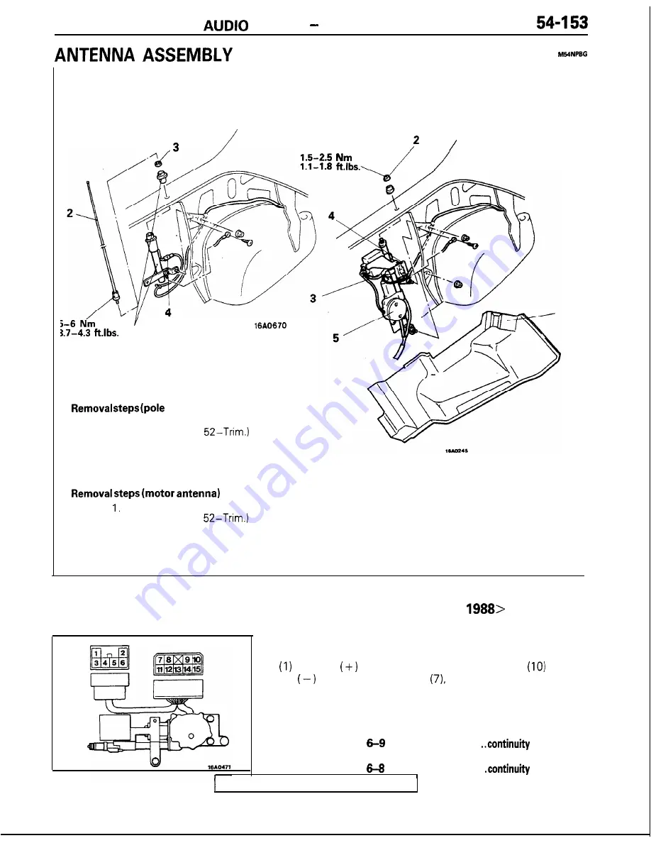
SYSTEM Antenna Assembly
Pole antenna
Motor antenna
1
5
antenna)
1. Trunk room side trim
(Refer to GROUP
2. Antenna mast
3. Ring nut
4. Feeder wire connection
5. Antenna base
Trunk room side trim
(Refer to GROUP
2. Ring nut
3. Harness connection
4. Feeder wire connection
5. Motor antenna assembly
INSPECTION
<Vehicles built up to June
MOTOR ANTENNA ASSEMBLY
F o l l o w i n g i n s p e c t i o n s s h o u l d b e m a d e w i t h t h e h a r n e s s
connector disconnected from the power antenna relay.
With the
power connected to the terminal
and the
power to the terminal
check that the antenna mast
extends. With the connection reversed, check that the
antenna mast retracts.
(2) Check for continuity between the terminals.
When the antenna mast is retracted
Between
. . . . . . . . . . . . . . . . . . . .
When
the antenna mast is extended
Between
. . . . . . . . . . . . . . . . . . . . .
TSB Revision


