THEFT-ALARM SYSTEM
Tool
Number
Name
Use
341
Scan tool (Multi-use
To check the input of the theft-alarm system
tester
ROM
pack
For the number, refer to GROUP
Before Service
Ground ETACS
From battery power
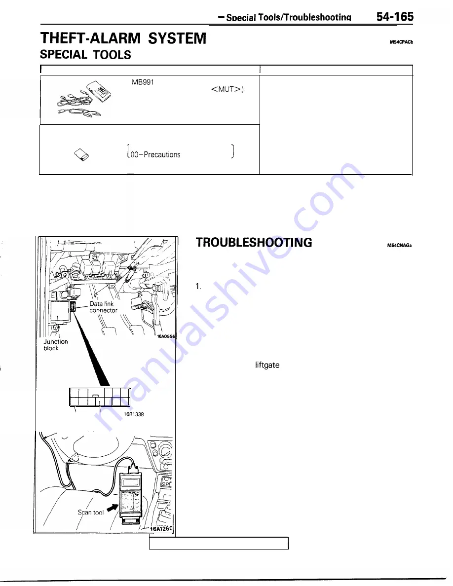
INPUT CHECK
Using a scan tool, check whether or not input signals are being
input from each switch to the electronic control unit.
Connect the scan tool to the data link connector (located at
the right side of the junction block).
2. Check to be sure that voltage should be output with the
ignition key “OFF”, door switch “ON” (door opening)
and
the following switch “ON”.
l
Key-reminder switch
l
Hood switch
l
Door switch
l
Door lock actuator switch
l
Door and
key cylinder switch
l
Trunk lid switch
If the buzzer does not sound, check for a malfunction of
that switch or for damaged or disconnected wiring.
TSB Revision