


IGNITION SWITCH
ignition Switch
54-7
Connector A
Connector
Key interlock cable
Apply grease
INSPECTION
IGNITION SWITCH INSPECTION
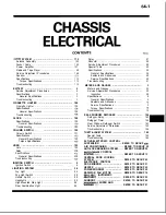
(1) Remove the instrument panel under cover (or knee
protector), the column cover (lower), and the column cover
(Refer to GROUP
Panel).
(2) Disconnect the wiring connector from the ignition switch
and key reminder switch, and connect an ohmmeter to the
switch side connector.
(3) Operate the switch, and check the continuity between the
terminals.
Ignition switch
reminder
switch
Position
3
4
2
5
1
7
8
9 1 2
Removed
LOCK
I
I I I
Inserted
o - u - o - - o
START
NOTE
(1)
indicates that there is continuity between the terminals.
(2) O---O indicates vehicles with ETACS.
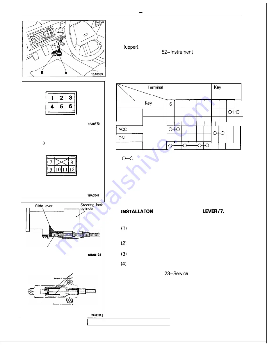
SERVICE POINTS OF INSTALLATION
8 .
O F T H E S L I D E
K E Y
INTERLOCK CABLE (STEERING LOCK ASSEMBLY
SIDE)
With the ignition key either at the “LOCK” position or
removed, install the slide lever to the steering lock
cylinder.
Connect, as shown in the figure, the key interlock cable
to the slide lever and the steering lock cylinder.
Apply a light coating of multi-purpose grease where
shown in the figure.
Check whether or not the key interlock system is
functioning normally.
(Refer to GROUP
Adjustment Procedures.)
TSB Revision
I