LIGHTING SYSTEM
Service
Adjustment Procedures
54-89
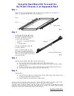
5
6
7
4
tire
1.
fixture
2. Thumb adjusting screws
3.
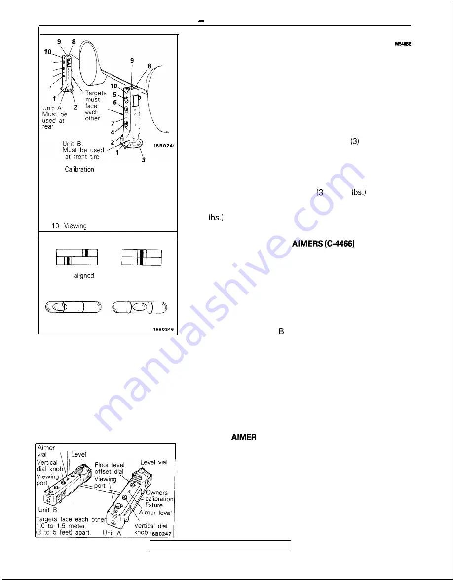
Level vial
4. Floor level offset dial
5. Horizontal dial knob
6. Vertical dial knob
7. Aimer level vial
8. Level vial bubble
9. Top port hole
port
Split image
not
Split image
aligned
Bubble not centered
Bubble centered
SERVICE ADJUSTMENT PROCEDURES
HEADLIGHTS AIMING
PRE-AIMING INSTRUCTIONS
1. Test dimmer switch operation.
2.
Observe operation of high beam light mounted in instru-
ment cluster.
3. Inspect for badly rusted or faulty headlight assemblies.
These conditions must be corrected before a satisfactory
adjustment can be made.
4. Place vehicle on a level floor.
5. Bounce front suspension through three
oscillations by
applying body weight to hood or bumper.
6. Inspect tire inflation.
7. Rock vehicle sideways to allow vehicle to assume its
normal position.
8.
If fuel tank is not full, place a weight in trunk of vehicle to
simulate weight of a full tank kg (6.5
per gallon].
9. There should be no other load in the vehicle other than
driver or substituted weight of approximately 70 kg (150
placed in driver’s position.
10. Thoroughly clean headlight lenses.
COMPENSATING THE
FOR FLOOR
SLOPE
The floor level offset dial must coincide with the floor slope for
accurate aiming. Calibration fixtures are included with the
aimers.
1. Attach one calibration fixture to each aimer. Fixtures will
easily snap into position on aimer when properly posi-
tioned.
2. Place aimers at
center line
of each wheel on one side of
vehicle. Unit A must be placed at rear wheel with target
facing forward. Unit must be placed at front wheel with
target facing rearward.
3. Adjust thumb adjusting screw on each calibration fixture by
turning either clockwise or counterclockwise until level vial
bubble registers in a centered, level position.
4.
Look into top port hole of Unit A. Turn horizontal knob until
split image is aligned.
5. Transfer plus or minus reading indicated on horizontal dial
to floor level offset dial on each aimer. Press floor level dial
inward to set reading.
6. Remove calibration fixtures from both units.
TESTING
CALIBRATION
The aimer calibration may be off due to extended use.
Calibration fixtures used in conjunction with aimers can be
used to check and adjust aimers.
1.
Turn thumb adjusting screw on each calibration fixture until
it is approximately the same distance as the supporting
posts.
2. Attach calibration fixtures to each unit with level vials on
top.
3.
Locate a true vertical plate glass window or smooth surface
and secure aimers three to five feet apart so split image
targets can be located in viewing ports
TSB Revision
level
Glass window or
vial smooth surface