background image

EN-13

Basic operation

Power ON procedures

1.  Turn the Main Power Switch on the rear of the product to ON to turn on the main 

power. 


The power lamp blinks green and then illuminates red. (You cannot turn on the power 
while the lamp is blinking green.) 

2.  Press the power ( ) button to turn on the power.
 

The power lamp illuminates green.

3.  Turn on the power of the other equipment.

CAUTION:

This monitor has the sensors to detect errors in the power, fan, temperature, and memory. When an error occurs, the power lamp 
illuminates. (See page 11.)

Power OFF procedures

1.  Press the power ( ) button to turn off the power.
 

The power lamp illuminates in red.

2.  Turn the Main Power Switch to the OFF mode.
 

The power lamp goes out.

NOTE:

For safety, unplug the power cord from the outlet. 
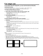
 

Image persistence

•  Please be aware that LCD Technology may experience a phenomenon known as Image Persistence. Image Persistence occurs 

when a residual or “ghost” image of a previous image remains visible on the screen. Unlike CRT monitors, LCD monitors’ im-
age persistence is not permanent, but constant images being displayed for a long period of time should be avoided. To alleviate 
image persistence, turn off the monitor for as long as the previous image was displayed. For example, if an image was on the 
monitor for one hour and a residual image remains, the monitor should be turned off for one hour to erase the image.

NOTE:

As with all personal display devices, we recommends displaying moving images and using a moving screen saver at regular inter-
vals whenever the screen is idle or turning off the monitor when not in use. 

Control by computer 

You can control this product using the control utility software installed on a personal computer to make settings such as picture qual-
ity adjustment. For the usage of the control utility software, see its operation manual. 
The control utility software and its operation manual are included on the CD-ROM that is supplied with the product.  

To view the operation manual of the control utility software, follow the steps below. 
1. Insert the CD-ROM supplied with the product into the CD-ROM drive. 
2. Open the 56PQF60LC folder from the CD-ROM. 
3. Double-click the Index.pdf icon. 
4. Select a language for the operation manual. 

Acrobat Reader/Adobe Reader is required to view the operation manual of the control utility software. If you don’t have it on your 
computer, you can download and install it from the Adobe website.

ON

OFF

Main Power Switch

(Rear panel)

Summary of Contents for 56P-QF60LCU

Page 1: ...o follow the directions below This product requires special installation to prevent falling or toppling Please ask installation specialists for installation Don t attempt to install the product by yourself This user s manual is important to you Please read it before using your product ...

Page 2: ...RVICEABLE PARTS INSIDE REFER SERVICING TO QUALIFIED SERVICE PERSONNEL The lightning flash with arrowhead symbol within an equilateral triangle is intended to alert the user to the presence of uninsulated dangerous voltage within the product s enclosure that may be of sufficient magnitude to constitute a risk of electric shock WARNING TO PREVENT FIRE OR SHOCK HAZARD DO NOT EXPOSE THIS APPLIANCE TO ...

Page 3: ... objects of any kind through openings of this product as they may touch dangerous voltage points or short out parts that could result in a fire or electric shock Never spill liquid of any kind on the product 14 Servicing Do not attempt to service this product yourself Refer all ser vicing to qualified service personnel 15 Damage requiring service Unplug the power cord from the wall outlet and refe...

Page 4: ...shielded control cable it may cause interference with radio and television reception Recommended Use For optimum performance allow 30 minutes for warm up Rest your eyes periodically by focusing on an object at least 5 feet away Blink often Clean the monitor surface with a lint free nonabrasive cloth Avoid using any cleaning solution or glass cleaner Flaws in the surface of the LCD panel cannot be ...

Page 5: ...CE NOTICE OF INDUSTRY CANADA This Class A digital apparatus complies with Canadian ICES 003 COMPLIANCE NOTICE OF EC DIRECTIVE This monitor complies with requirements of 89 336 EEC 2006 95 EC and 93 68 EEC The requirements of susceptibility have chosen at a level that makes interference free operation possible in living areas office areas and light industry related to indoor and outdoor operation A...

Page 6: ... lamp Receives the signal from the remote control when using the optional wireless remote control During start up it will blink green Glows red when the LCD is in stand by mode and glows green when the monitor is in active When the LCD is in power save mode it will glow both green and red In the case of where a failure is detected it will blink red Refer to page 11 Front panel ...

Page 7: ...or Connects with the power cord 3 INPUT 1 4 DVI D x 4 Connect the DVI D cable with the DVI D connector of the computer 4 RS 232C connector Connect the RS 232C cable with the RS 232C connector of the computer for control the monitor 5 LAN connector Connect the LAN cable with the LAN connector of the com puter for control the monitor Rear panel ...

Page 8: ...res to prevent the monitor from falling over in case of an earthquake or other disaster to lessen the probability of injury and damage resulting from fall As shown in the figure secure the monitor to a solid wall or pil lar using rope commercially available strong enough to bear the weight of the monitor Approx 51 kg CAUTION Attach the ropes and screws securely When mounting the monitor on the wal...

Page 9: ...creasing the effect of lowering the temperature of the product The factory default is NORMAL When the temperature inside the product exceeds a certain level the cooling fan changes the rotation speed from Low to High Control application CONFIGURATION FAN MODE NORMAL FULL 2 Bright mode You can adjust the brightness of the screen When NORMAL is selected the brightness is automatically lowered to 80 ...

Page 10: ...ates at a high speed Control application CONFIGURATION FAN MODE NORMAL FULL 2 Installation conditions For standard installation Install the product on a flat surface When the panel surface bends or curls uneven brightness and uneven color tend to be caused degrading the screen uniformity For good ventilation leave space around the product as much as possible Don t block the intake and exhaust vent...

Page 11: ...lications This product is designed for indoor use Protective measures for outdoor use such as water proofing moisture proofing dust proofing salt resistance and UV resis tance resistance to sunlight irradiation aren t provided to the product This product isn t designed for use in vehicles and boats Because this product doesn t comply with any automobile standards and isn t designed to be resistant...

Page 12: ...to each of INPUT 1 to 4 connectors The image of 2544x1080 signal can not display correctly Images may not be displayed correctly depending on the type of video card or driver Signals input to INPUT 1 to 4 connectors are laid out on the screen as follows Connect the power cord 1 Insert one end of the power cord into the power input connector of this product Insert it as far as it will go 2 Clamp th...

Page 13: ... alleviate image persistence turn off the monitor for as long as the previous image was displayed For example if an image was on the monitor for one hour and a residual image remains the monitor should be turned off for one hour to erase the image NOTE As with all personal display devices we recommends displaying moving images and using a moving screen saver at regular inter vals whenever the scre...

Page 14: ...characteris tics of the LCD panel Lines aren t displayed in correct width This symptom may occur when an image of other than 3840x2160 resolution is displayed This is not a failure but due to the characteristics of the LCD panel Afterimage appears on the non display area This symptom may occur when the entire monitor isn t filled with the display area and the same image is kept displayed for a lon...

Page 15: ...Separate HV sync TTL level Signal input connector DVI D Operational environment Temperature 5 35 C Humidity 20 80 Without condensation Storage environment Temperature 20 55 C Humidity 20 80 Without condensation Power Power supply AC 100 240 V 50 60Hz 5 5 A Power consumption Max 550 W Power connector 3P IEC type Weight 51 kg Approximately Accessories User s manual Gross 68 kg 1452 W x 1020 H x 582 ...

Page 16: ...l Clock 18 TX 0 7 DDC Serial Data 19 Shield TX0 TX5 8 NC 20 NC 9 TX 1 21 NC 10 TX 1 22 Shield TXC 11 Shield TX1 TX3 23 TXC 12 NC 24 TXC 2 RS 232C input output Pin No Name 1 NC 2 RXD 3 TXD 4 NC 5 GND 6 NC 7 RTS 8 CTS 9 NC 3 LAN terminal Pin No Name 1 TX 2 TX 3 RX 4 NC 5 NC 6 RX 7 NC 8 NC D SUB 9P 5 6 1 9 DVI D 24 pin 8 1 9 16 17 24 Pin Assignment 1 8 ...

Page 17: ...871D502A30 Printed in Japan 1 Zusho Baba Nagaokakyo City Kyoto Japan MITSUBISHIELECTRICCORPORATION ...

Reviews: