α
2 Simple Application Controllers
Function Blocks 6
6 - 53
6.22
PID Block
The PID Function Block contains the
α
2 implementation of PID, a control method used to
obtain stable control over a system variable. The chapter describes, in detail, the necessary
parameter adjustments for using the PID Function Block properly. A simpler alternative is to
run the Auto-tuning function, which automatically adjusts the parameters for the specific
system. The following terms will be used throughout this chapter, Process Value (PV), Set
Value (SV) and Manipulated Value (MV). The PV is the current measured value of the system
parameter that PID is controlling. SV is the desired value of the parameter being controlled and
MV is the output of the PID Function Block used to drive the PV to the SV. Up to 20 PID
Function Blocks may be used in a program.
Table 6.23:
PID Block
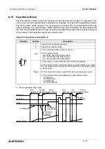
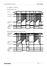
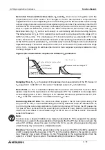
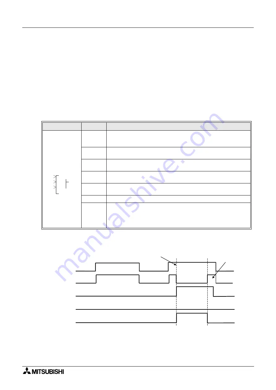
PID Function Block Operation - Timing Diagrams
1) PID Operation when Auto-tuning has finished normally.
Function
Set Item
Description
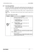
E
Enable pin for the PID Block. The Error output is reset when the pin
goes OFF. If left unconnected, the function block will always be
enabled.
A
Starts Auto-tuning on the transition from OFF to ON. If the pin is
unconnected it is considered OFF.
C
Clears all output signals and stops Auto-tuning, when turned ON. If
left unconnected, the pin is considered to be OFF.
SV
The word input pin for the set value. If left unconnected a set value of
0 is used in the control calculations.
PV
The word input pin for the process value. If left unconnected a
process value of 0 is used in the control calculations.
FB
Refer to the Timing Diagrams and Parameter Settings below.
Output
1) AT RUNNING turns on when auto-tuning is in operation.
2) The following outputs are available for other function blocks:
a) MV (Manipulation Value)
b) ERROR CODE
0
0
0
I
P
O
A
D
P
E
C
EN
AT
AT RUNNING
CLEAR
AT start
operation performed
with new parameter
PID operation

