α
2 Simple Application Controllers
Function Blocks 6
6 - 62
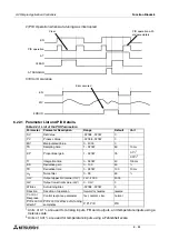
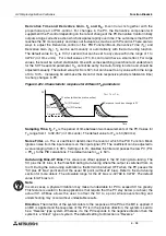
Response when T
I
is increased:
The PV stabilizes slowly with less searching (overshoot and undershoot) for the SV.
Response when T
D
is increased:
The PV stabilizes quickly. There is more searching (overshoot and undershoot) for the SV.
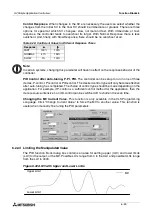
6.22.7 Error Codes
Error Codes are reported by the PID Function Block via the string output pin. The error code
byte consists of 8 error flags, but only the lower 6 bits are functional. An error code value of
zero means there is no error.
1.
This is the maximum change in PV when the input filter is 0%. In the case of a higher input
filter, the maximum change in PV can be higher.
2.
Bit 5 of the error code is set when the calculated PID parameters are out of range. Bit 5 is not
set when AT is stopped by the user.
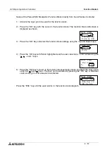
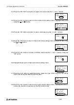
Setup of the PID Function Block directly from the
α
2
Series Controller
1 ) Allocate the input pin to be used for the function block.
2 ) Press the “OK” key with the cursor in the function block. The function block edit screen is
displayed as shown.
3 ) Press the “OK” button to setup the parameters for the PID function block.
4 ) Highlight SetValue and select it using the “OK” button. Choose from DirectSet, Analog In,
or FB Value for the Set Value of the PID function block.
Table 6.30:
Bit
Content
State of processing
b0
Sampling time < (system) scan time
PID operation continued
b1
Filtered PV change overflow
(
∆
PV
fn
< -21692 or
∆
PV
fn
> 21692)
1
b2
Deflection overflow (EV < -32768 or EV > 32767)
b3
Integration result overflow (out of range: [-32768, 32767])
b4
Derivative overflow (out of range: [-32768, 32767])
b5
2
Internal error during auto-tuning operation
AT ends
S e t u p
B
C h a n g e
B 0 0 1 : P I
F
D
N o
D e l e t e
F B
S e t
a
V
u
P r o c e s
B 0 0 1 : P I
l
D
a
V
S a mp l e
T i
e
s
l
me
D i r
t
c
e
A n a l o g
B 0 0 1 : P I
S
D
n
I
F B V a l
e
t
u
e


