α
2 Simple Application Controllers
Let’s Make a Program 7
7 - 2
7.3
Input the Program
The options are set and the Function Block diagram is finished. It is time to start inputting the
program. From the TopMenu enter ProgEdit to begin programming using the front keys as
described in Chapter 4 Direct Programming.
If during the course of the programming you wish to begin again, use the “ESC” key to enter
the Edit Menu. Use the Exit option to go back to the TopMenu. Erase the memory using
ProgClear and the user can begin again.
7.3.1
Adding Function Blocks by the Left to Right method (Section 4.2.1)
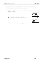
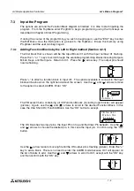
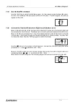
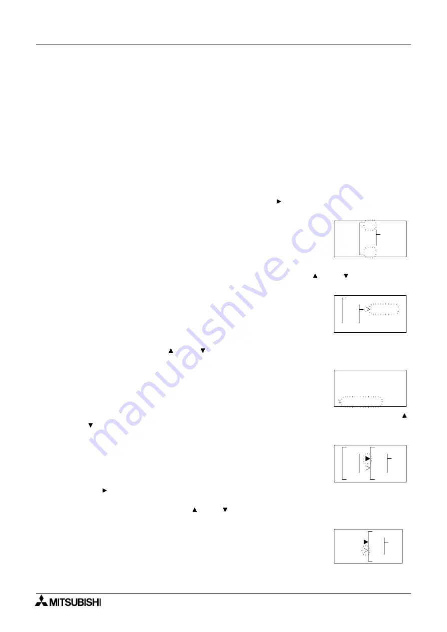
The first block that is shown will be the Input Block I01 with the Input number 01 flashing.
Press the “+” or “-” keys to scroll through the available programming blocks including Outputs,
M bits, Keys, and the Inputs. Return to I01. Press the ( ) arrow key. The output pin should
now be flashing.
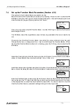
Press “+” to attach a function block to Input I01. The options available to connect to the Input
block will be shown on the right hand side of the screen. Use the ( ) and ( ) arrows to move
to the option to select, AddFB. Enter “OK”.
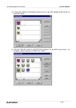
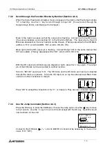
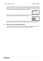
The FB select menu containing all 35 Function Blocks
(including logic blocks) will appear
(picture). Again, use the ( ) and ( ) arrows to scroll to the desired Function Block, in this
case the One Shot (OS) Function Block. Use the “OK” button to accept.
The OS block has two input pins, the Input Pin on top and the Clear Pin beneath. Use the ( )
and ( ) arrows to choose the desired pin, in this case the Input pin. Confirm using the “OK”
button.
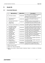
Use the ( ) arrow twice to move right until the OS output pin is flashing (picture). Enter the “+”
key to add a block. There is no need to enter the AddFB mode because O01 will appear on
the list of blocks to add. Use the ( ) and ( ) arrows to scroll to O01, accept with the “OK” key,
and then confirm with the “OK” key.
1
n
I
0
1
o
C
0
n
n
c
e
t
d
A
F
d
B
0
O 1
e
l
e
S
B
F
t
L
A
t
e
e
R
t
k
c
i
e
n
O
r
e
F l
n
h
S
t
o
c
1
0
n
I
0
1
0
P
S
O
0
1
0
P
S
O

