α
2 Simple Application Controllers
Let’s Make a Program 7
7 - 3
7.3.2
Scroll through the Function Blocks by Number (Section 4.6.1)
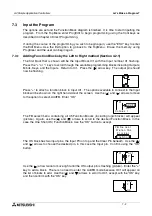
When the Output has been connected, move one space to the right so that the Output number
“01” is flashing. Use the “+” key to scroll through to Input I02. (You will scroll through the
Outputs, Keys, M bits, and finally get to the Inputs).
Move to the right one space so that the output pin is flashing. Connect I02 to the OR block,
(the same procedure as connecting I01 to the One Shot Block). The input pins for the OR
Block are equivalent so that any input pin can be chosen. [The key sequence for the OR Block
addition is “OK”, scroll to AddFB, “OK”, scroll to OR, OK, OK].
Move right until the OR output pin is flashing. Connect Output O03 in the same manner that
O01 was added. [The key sequence will be “OK”, scroll to O03, OK, OK].
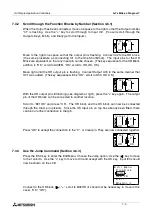
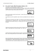
With the OR output pin still flashing (see diagram at right), press the “+” key again. The output
pin of the OR block can be connected to another location.
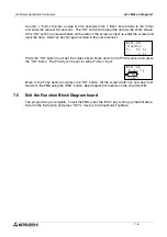
Scroll to “B01OS” and press “OK”. The OR block and the OS block can now be connected
through the Clear pin (picture). Since the OS Input pin on top has already been filled, there
can be no further connection to that pin.
Press “OK” to accept the connection to the “C”, or Clear pin. They are now connected together.
7.3.3
Use the Jump Command (Section 4.6.3)
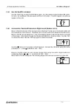
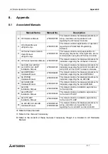
Press the ESC key to enter the Edit Menu. Choose the Jump option. Use the ( ) key to move
to the I column. Use the “+” key to move to I03 and accept with the OK key. Input I03 should
now be shown on the LCD.
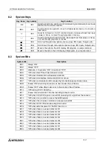
Connect to the OR block [( ), “+”, scroll to B02OR (it should not be necessary to move in this
case), “OK”, “OK”].
0
0
S
O
0 1
u
O
1
P
t
0
0
R
O
0 3
u
O
2
t
n
n
R
O
P
S
O
o
C
t
c
e
0
0
R
O
P
S
O
2
0
0
1
e
M
u
n
e
z
i
t
d
E
i
p
m
w
e
N
J u
S
g
o
r
P
i
x
E
t
B
F
c
i
n
o
m
e
n
M


