α
2 Simple Application Controllers
System Menu 3
3 - 23
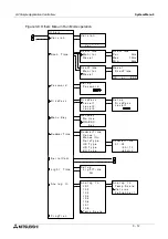
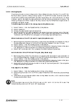
To change the temperature scale setting (Stop Mode only):
1 ) Select “Others...” from the TopMenu while in Stop Mode.
2 ) Select “Analog In.”
3 ) Select “TempScale.”
4 ) Select “Celsius” or “Fahrenheit.”
Note:
In Run Mode, the temperature scale can be checked but cannot be changed.
Note:
System flags, M17 through M24, correspond to the 8 possible temperature input channels, I01
through I08. When the analog input is configured for TC or PT100 input, these system flags will
detect a defect in the ADP module’s operation. An input voltage of more than 11 volts will set
the corresponding flag and indicates a sensor problem. An input voltage of 0 volts will also set
the corresponding flag, but indicates a power failure at the ADP module.
3.7
LCD Displays
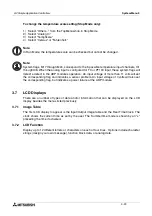
There are a number of types of data and/or information that can be displayed on the LCD
display besides the menus listed previously.
3.7.1
Image Table
The first LCD display to appear is the Input/Output image table and the Real Time Clock. The
clock shows the current time as set by the user. The Summertime mode is shown by an “s”
preceding the time if activated.
3.7.2
LCD Function
Display up to 12 different letters or characters on each of four lines. Options include character
strings (design your own message), function block data, or analog data.

