α
2 Simple Application Controllers
System Menu 3
3 - 24
3.8
Block Items
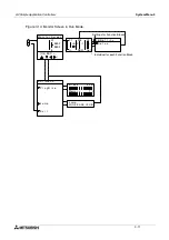
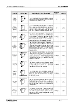
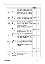
Each block item contains an individual diagram that shows the block number, available number
of input pins, the output pin if applicable, and the block mnemonic. Connections between
blocks can be viewed at the pin locations when connected blocks are shown individually on the
LCD.
3.8.1
Input Blocks
The Input Blocks consist of System Inputs (I01 - I15), Key Inputs (K01-K08), and System Bits
(M01-M14). The input number is shown in the top right hand corner, the type of input in the
lower right hand corner, and the output pin is shown on the far right of the block. Input Blocks
provide information to the Function Blocks or Outputs.
3.8.2
Function Blocks
The individual Function Blocks are described in detail in Chapters 5 and 6. Function Blocks
can have 0 to 4 input pins shown on the left of the diagram and an output shown on the far
right. Some function blocks have data that can be used for comparison purposes only or are
used to display data onscreen. These blocks have no output pins. The number and block
mnemonic are shown in the top right and bottom right locations respectively.
3.8.3
Output Blocks
Output Blocks have one input and one output pin. They only have the capacity for one input
signal through the input pin. The Output Block number and Mnemonic are shown in the top
right and lower right hand corner of the diagram respectively.
3.8.4
Connected Blocks
Blocks that are connected can be shown simultaneously onscreen. The block providing the
output signal will be shown on the left of the screen. The input pin accepting the signal will
flash. Any input pin that is already connected will be shown as a solid triangle.


