6 - 6 6 - 6
MELSEC-GOT
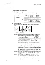
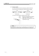
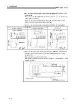
6 HANDLING
6.1.4 Wiring precautions the part which matches the EMC Directives
Connect and wire GOT-A900 series equipment as instructed below.
If the GOT-A900 series equipment is configured in a way that differs from the following
instructions then the system will not comply with EMC directives.
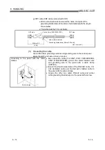
(1) Method to connect the power wire, ground wire and protective
ground terminal
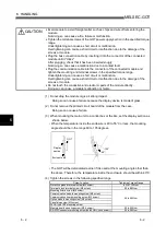
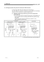
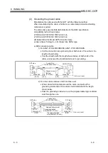
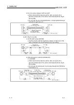
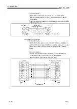
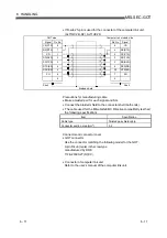
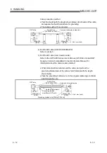
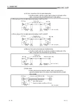
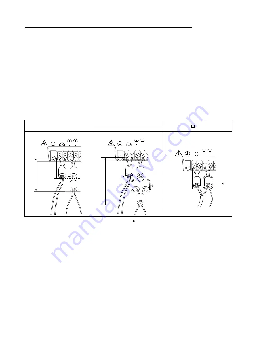
a) Connect the power wire and connection cable as shown in the illustration, and
be sure to attach a ferrite core (TDK type ZCAT3035-1330) within the range
shown below.
Lead the power wire and ground wire as shown in Section 1.1.2 (2).
Always ground the LG and FG wires.
For A985GOT
For Bus connection
For RS-422 connection
A97 /960GOT
INPUT
100-240VAC
(LG)
(FG)
AC
LG
FG
GOT terminal block
Ferrite
core
within 100mm
(3.94 inch)
within 50mm
(1.97 inch)
INPUT
100-240VAC
(LG)
(FG)
AC
LG
FG
GOT terminal block
Ferrite
core
1
within 100
mm
(3.94
inch)
within 50
mm
(1.97 inch)
INPUT
100-240VAC
(LG)
(FG)
AC
LG
FG
GOT terminal block
1
Ferrite
core
within 90mm
(3.54 inch)
1: Wrap the FG and LG wire around the ferrite core.

