6 - 25 6 - 25
MELSEC-GOT
6 HANDLING
6.6 Communication Board
The communication board is used to make the GOT interface compatible with the
system to be connected to.
For the details of the connection form, refer to the [GOT-A900 Series User's Manual
(GT Works Version5/GT Designer Version5 compatible Connection System Manual)].
6.6.1 Connection board types
The following connection board types are available.
Type
Description
A9GT-QBUSS
For bus connection, small connector type (For QCPU (Q mode))
A9GT-QBUS2S
For multidrop bus connection, small connector type (For QCPU (Q mode))
A9GT-BUSS
For bus connection, small connector type (For A/QnA/Motion controller CPU)
A9GT-BUS2S
For multidrop bus connection, small connector type (For A/QnA/Motion controller CPU)
A9GT-RS4
For Direct connection to CPU/Computer link connection/Microcomputer connection and
RS-422 connection (Without clock function)
A9GT-RS2
For Direct connection to CPU/Computer link connection/Microcomputer connection and
RS-232C connection (Without clock function)
A9GT-RS2T
For Direct connection to CPU/Computer link connection/Microcomputer connection and
RS-232C connection (Incorporating clock function)
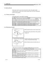
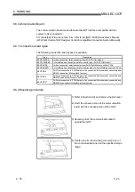
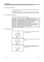
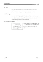
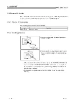
6.6.2 Mounting procedure
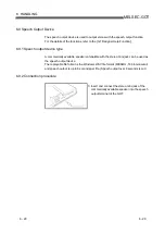
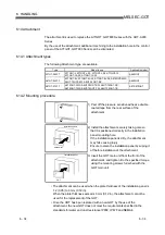
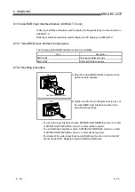
1) Refer to [Section 6.2] and remove the slot cover.
2) Insert the convex portion of the communication
board into the concave portion of the GOT.
3) Securely press the communication board
against the GOT.
4) Tighten and fix the mounting screws (2 pcs.) of
the communication board in the specified torque
range.

