E-30
15. Cell switch (CL)
15.1 How to check the speci
fi
cations
15.2 How to connect terminals
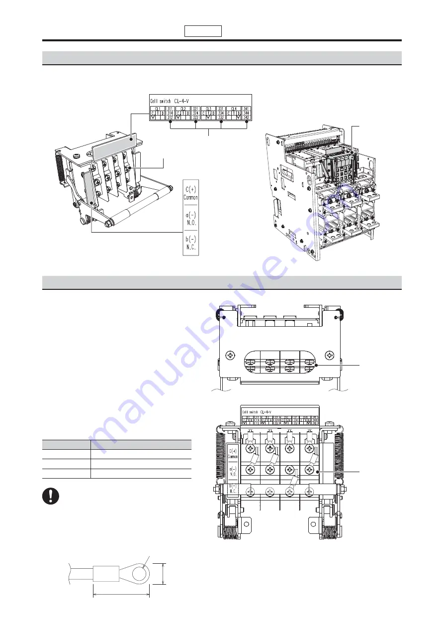
The terminal screws on the cell switch are arranged corresponding to the terminal numbers on the rated nameplate.
Connect the wire to the terminal block within
the specified tightening torque. The following
table lists the drawout position depending on
the specifications of the cell switch.
Wire the lead wires through the lead wire hole
on the top of the circuit breaker and fix them in
the terminal block with screws.
When wiring, do not damage the lead wires. Wire
them so that the excessive tension is not applied
to them when the circuit breaker operates.
After wiring, check that the wires do not interfere
with the operation of the circuit breaker and
the output properly switches depending on the
drawout position.
The terminal screws are M4 binding head
screws. The following figure shows an available
solderless terminal.
Nameplate 2
Drawout type
Cell switch
Terminal screw
* In case of CL: 2C1T1D
Terminal number
Nameplate 1
Terminal screw (M4)
Tightening torque: 0.98
±
0.2 N
・
m
Lead wire hole
Terminal block
(Note)
Overtightening can cause damage to
the terminals and/or screws.
Specifications
Position for the drawout operation
CL-C
CONNECT
CL-T
TEST
CL-D
DISCONNECT
20 mm or shorter
ȭ
4.3
8 mm
Option


