Air Handling Unit Interface
AHU-KIT-SP
MORIKAWA
SPECIFICATION
PSZ000Z308
15/38
MODEL NAME
MODEL TYPE
ISSUE
CLASSIFICATION
DWG NO.
REV.MARK PAGE
21.09.17
100
R
e
q
u
ir
e
d
c
a
p
a
c
it
y
c
o
n
to
l
c
o
m
m
a
n
d
[
%
]
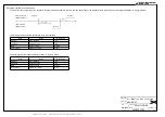
Analog input current [mA]
20
0
0
4
19.5
100
R
e
q
u
ir
e
d
c
a
p
a
c
it
y
c
o
n
to
l
c
o
m
m
a
n
d
[
%
]
Analog input voltage [V]
10
0
0
9.0
1
●
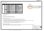
Analog input circuit
・
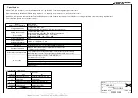
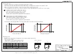
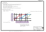
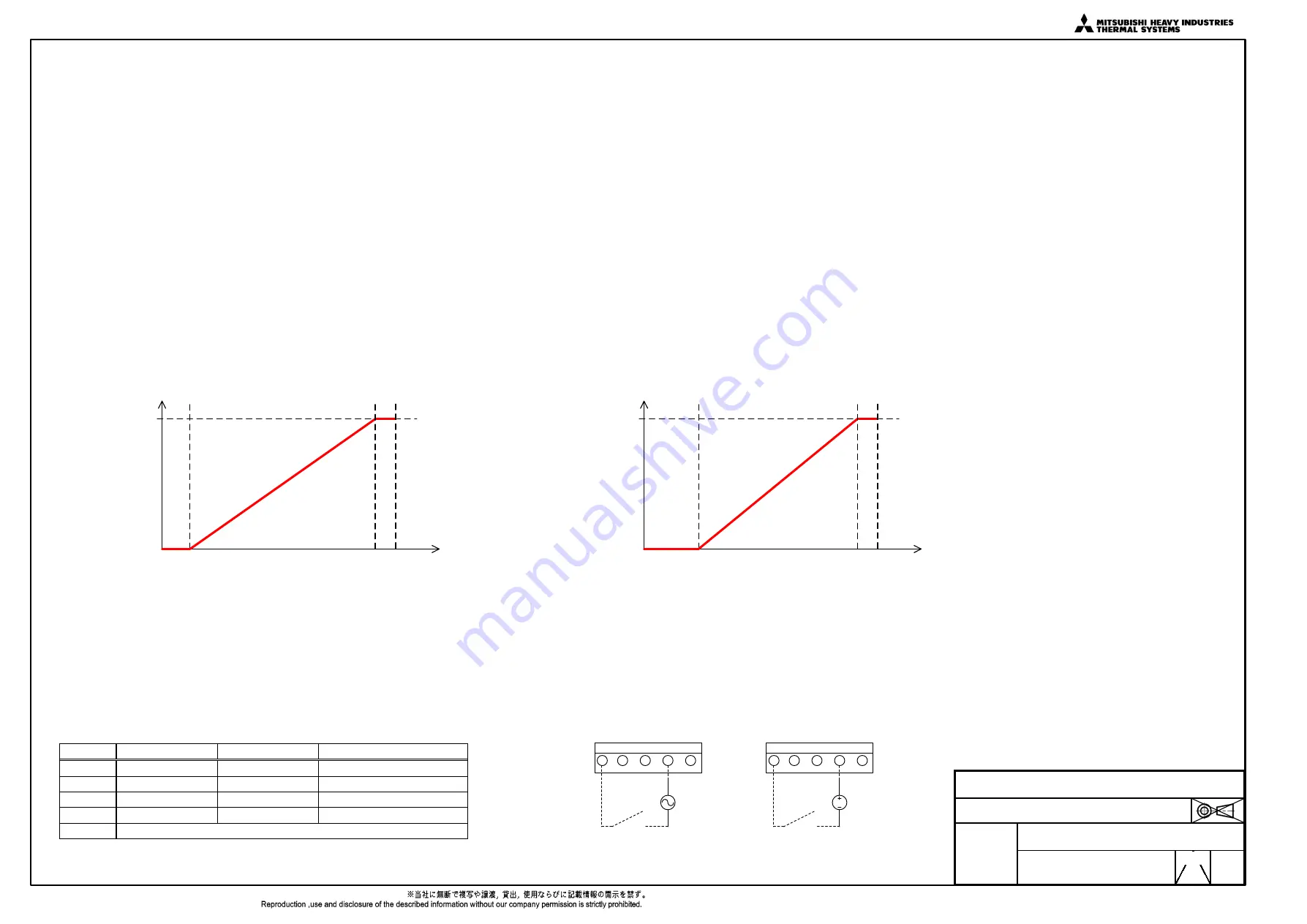
Compressor speed can be controlled by the analog input signal (0–10V / 4–20mA).
AHU interface converts 0–10V/4–20mA signal into the 0–100% range to understand how much capacity are required as a AHU.
Outdoor unit operates with the maximum compressor speed when 100% required capacity is used.
To use analog input function, make sure you enable the capacity control by configuring DIP SW7-4 as "OFF" (see 5 for more details).
①
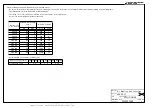
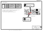
0–10V Capacity Control (SW7-1: OFF and JX2 1-2 short)
0–10V signal is regarded as a required capacity of 0–100%.
Please note that there is a dead band in certain ranges.
(ex) When 0.5V is input, it would be regarded as 0% required capacity.
②
4–20mA Capacity Control (SW7-1: ON and JX2 2
–
3 short)
4–20mA signal is regarded as a required capacity of 0–100%.
Please note that there is a dead band in certain ranges.
(ex) When 0.9V is input, it would be regarded as 0% required capacity.
・
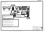
The analog input signal: 0–10[V]/4–20[mA] controls the required capacity of the outdoor unit in the following range.
●
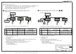
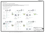
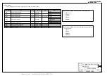
Digital input circuit
・
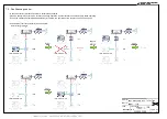
ON/OFF can be recognised by the changing edge of the voltage to the digital input terminal.
・
X2-5 is a common terminal.
When using X2-1 to X2-4, wire them together with X2-5.
・
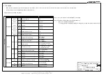
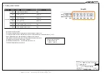
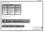
The functions of the digital input terminals are as follows.
Terminal
Function
ON
OFF
X2-1
Run/Stop
Run
Stop
X2-2
Cooling/Heating
Heating
Cooling
X2-3
Emergency stop
Emergency stop
Emergency stop release
X2-4
Reserve
-
-
X2-5
Common
X2
Digital input:Example X2-2
Power supply
AC24V-240V
AC
DC
X2
Power supply
DC20V-130V
1
2
3
4
5
1
2
3
4
5


