


Revision C system board
Chapter 4
Appendix A
Appendix C
Pr
eface
B/2 LS PRO HARDWARE TECHNICAL REFERENCE
Chapter 6Chapter 4Appendix B
CL-GD5410
The video adapter on revision C of the LS Pro system board is based on a Cirrus Logic
CL-GD5410 chip. The CL-GD5410 contains all the elements of a VGA controller,
except display memory, providing 100% compatibility with the IBM VGA standard.
The video adapter consists of the GD5410 video controller, 1 Mbyte of display
memory, a frequency synthesizer and a 7.6mA current reference.
The frequency synthesizer is controlled by the GD5410 and is used to generate the
video clocks for all video modes. Video dot clocks vary from 25 to 65 MHz depending
on video mode.
Software support is provided by a video BIOS included in the system BIOS.
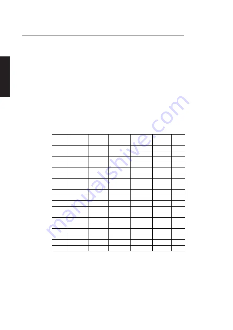
In addition to full compatibility with the VGA standard the GD5410 supports a range
of enhanced video modes. Seven enhanced modes are supported in the BIOS.
The video modes available are given in the following table:
Mode
Type
Colours
Displayed
Chars
Character
Cell
Pixels
Note
0, 1
Text
16/256K
40x25
9x16
360x400
2, 3
Text
16/256K
80x25
9x16
720x400
4, 5
Graphics
4/256K
40x25
8x8
320x200
6
Graphics
2/256K
80x25
8x8
640x200
7
Text
-
80x25
9x16
720x400
D
Graphics
16/256K
40x25
8x8
320x200
E
Graphics
16/256K
80x25
8x8
640x200
F
Graphics
-
80x25
8x14
640x350
10
Graphics
16/256K
80x25
8x14
640x350
11
Graphics
2/256K
80x30
8x16
640x480
12
Graphics
16/256K
80x30
8x16
640x480
13
Graphics
256/256K
40x25
8x8
320x200
2E
Graphics
256/256K
80x30
8x16
640x480
1
30
Graphics
256/256K
100x37
8x16
800x600
1
37
Graphics
16/256K
128x48
8x16
1024x768
1
38
Graphics
256/256K
128x48
8x16
1024x768
1
64, 6A
Graphics
16/256K
100x37
8x16
800x600
1
7A
Graphics
64K/64K
80x30
8x16
640x480
1
7B
Graphics
64K/64K
100x37
8x16
800x600
1
Notes
1. These are enhanced video modes.
Sync signals output to the monitor are at TTL levels while the analogue video outputs
are at 0 to 0.7 volts.
Summary of Contents for Apricot LS Pro
Page 1: ...apricot HARDWARE TECHNICAL REFERENCE MITSUBISHI ELECTRIC LS Pro ...
Page 2: ...HARDWARE TECHNICAL REFERENCE ...
Page 6: ...CONTENTS ...
Page 9: ...Chapter 1 INTRODUCTION ...
Page 14: ...Chapter 2 SYSTEM UNIT ...
Page 37: ...Chapter 3 SYSTEM BOARD ...
Page 60: ...Chapter 4 PERIPHERAL ITEMS ...
Page 91: ...Chapter 5 MEMORY AND I O USAGE ...
Page 118: ...Appendix A SPECIFICATIONS ...
Page 125: ...Appendix B REVISION C SYSTEM BOARD ...
Page 130: ...ERROR BEEP CODES Appendix C ...
Page 134: ...INDEX ...


