


System unit
2/2 LS PRO HARDWARE TECHNICAL REFERENCE
Contents
Chapter 2
Chapter 2
Chapter 6
Chapter 3
Chapter 2
Chapter 5
Introduction
The main components of the system unit are:
•
base
•
top cover
•
system board
•
disk drives
•
power supply
The top cover is easily removed without any tools.
The system board contains all the processing and interface circuitry and the system
RAM. 2 or 4 Mbytes of RAM is soldered to the board and SIMMs can be fitted to increase
the total amount of system RAM to a maximum of 16 Mbytes.
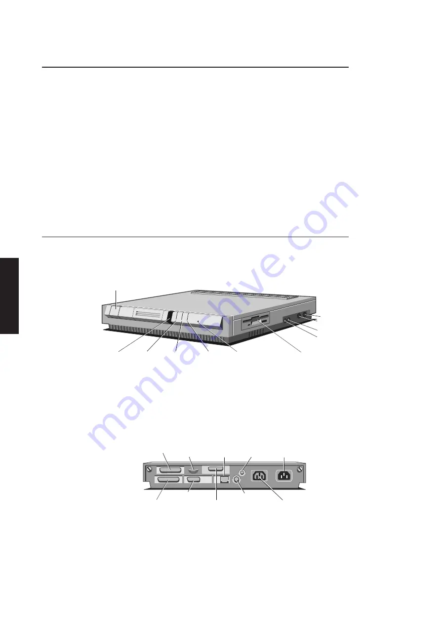
External layout
The front panel of the system unit contains: the power switch and slots for four LEDs
and the IR detector for the security card. The right side panel contains the keyboard
and mouse ports, and the audio input and output sockets.
POWER SWITCH
INFRARED
SENSOR
FLOPPY
DISK DRIVE
POWER
INDICATOR
LAN
INDICATOR
FLOPPY DISK
INDICATOR
HARD DISK
INDICATOR
MOUSE
KEYBOARD
AUDIO IN
AUDIO OUT
The floppy drive bezel is on the right side of the system unit.
The rear panel contains the following connectors: mains power input; auxiliary power
outlet; monitor; Ethernet ports; serial port; parallel port.
The layout of the rear panel is shown in the illustration below.
THIN
ETHERNET
PORT
PARALLEL
PORT
COVER
LOCK
SERIAL
PORT
SECURITY
LOOP
POWER
OUT
POWER
IN
VIDEO
PORT
THICK
ETHERNET/
TOKEN RING
PORT
TWISTED
PAIR ETHERNET
Illustrations and pinouts of the connectors on the rear panel are given at the rear of
this section.
Summary of Contents for Apricot LS Pro
Page 1: ...apricot HARDWARE TECHNICAL REFERENCE MITSUBISHI ELECTRIC LS Pro ...
Page 2: ...HARDWARE TECHNICAL REFERENCE ...
Page 6: ...CONTENTS ...
Page 9: ...Chapter 1 INTRODUCTION ...
Page 14: ...Chapter 2 SYSTEM UNIT ...
Page 37: ...Chapter 3 SYSTEM BOARD ...
Page 60: ...Chapter 4 PERIPHERAL ITEMS ...
Page 91: ...Chapter 5 MEMORY AND I O USAGE ...
Page 118: ...Appendix A SPECIFICATIONS ...
Page 125: ...Appendix B REVISION C SYSTEM BOARD ...
Page 130: ...ERROR BEEP CODES Appendix C ...
Page 134: ...INDEX ...


