


System unit
Contents
Chapter 2
Chapter 5
Chapter 6
Chapter 3
Chapter 2
2/12 LS PRO HARDWARE TECHNICAL REFERENCE
Chapter 2
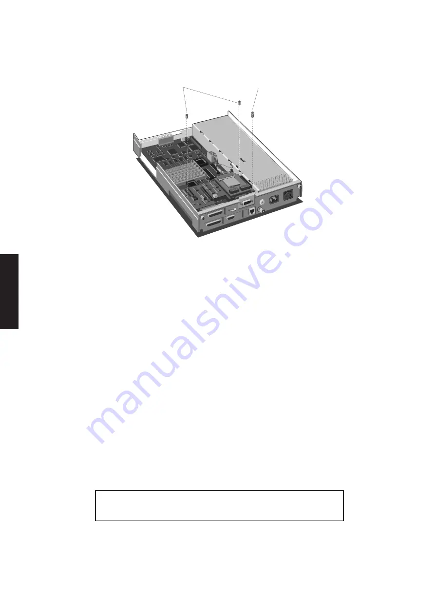
3. Remove the screws and nuts which secure the module to the standoff pillars.
SECURING
NUTS
SECURING
SCREW
4. Gently remove the module.
Note
Care must be taken to ensure that the module is removed vertically. Any horizontal
movement will damage the connectors.
Read the following paragraphs before replacing the module.
The Token-Ring module connectors have three components: the connectors on the
system board, the connectors on the Token-Ring module, and the pin assemblies which
connect them. When you remove the Token-Ring module the pin assemblies will
probably come out with the Token-Ring module, although they may remain in the
system board.
When the Token-Ring module is in position the plate that surrounds the Token-Ring
connector is between the system unit base and the escutcheon plate. The two standoff
pillars by the connector nearest the power supply, protrude through corresponding
holes in the Token-Ring module.
It is vital that during replacement the Token-Ring module is correctly aligned. Any
misalignment will damage the connectors and/or the module. When replacing the
module make sure that the plate is inserted correctly and that the standoff pillars are
correctly aligned. Check that the connectors are correctly aligned, then gently insert
the module.
Warning
Take care not to exert undue pressure when inserting the module.
Summary of Contents for Apricot LS Pro
Page 1: ...apricot HARDWARE TECHNICAL REFERENCE MITSUBISHI ELECTRIC LS Pro ...
Page 2: ...HARDWARE TECHNICAL REFERENCE ...
Page 6: ...CONTENTS ...
Page 9: ...Chapter 1 INTRODUCTION ...
Page 14: ...Chapter 2 SYSTEM UNIT ...
Page 37: ...Chapter 3 SYSTEM BOARD ...
Page 60: ...Chapter 4 PERIPHERAL ITEMS ...
Page 91: ...Chapter 5 MEMORY AND I O USAGE ...
Page 118: ...Appendix A SPECIFICATIONS ...
Page 125: ...Appendix B REVISION C SYSTEM BOARD ...
Page 130: ...ERROR BEEP CODES Appendix C ...
Page 134: ...INDEX ...


