


Chapter 2
Chapter 6
Contents
Chapter 2
Chapter 5
System unit
Chapter 3
Chapter 2
LS PRO HARDWARE TECHNICAL REFERENCE 2/13
Removing a
The parallel port cable is secured to the escutcheon plate by the two D-type
parallel port
connector screwlocks. To remove the cable:
cable
1. Remove the system board metalwork.
2. Remove the two screwlocks in the parallel port connector.
3. Unplug the cable from the socket on the system board and lift the cable clear.
4. Replacement is simply the reverse of removal.
Removing a thick
The thick wire Ethernet assembly is secured to the escutcheon plate at the rear of
wire Ethernet
the system unit. To remove the assembly follow the instructions below:
assembly
1. Remove the system board metalwork.
2. Remove the screw that secures the thick wire Ethernet assembly to the
escutcheon plate, unplug the assembly cable from the system board, and lift the
assembly clear of the system unit.
3. Replacement is simply the reverse of removal.
Removing the
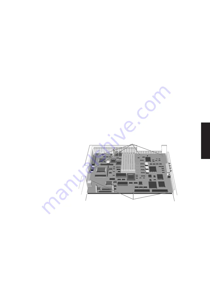
The system board is secured to the base of the system unit by seven screws through
system board
the system board and four screwlocks through the escutcheon plate. The following
illustration identifies the positions of the system board screws.
SECURING SCREWS
SECURING SCREWS
1. Remove the system unit top cover and put the system cover lock in the locked
position.
2. Remove the system board metalwork and disconnect all system board connectors.
3. Remove the parallel port cable and thick cable Ethernet assembly or Token-Ring
module (if fitted).
4. Remove the seven screws which secure the system board.
5. Remove the screwlocks that secure the video and serial port connectors.
6. Remove the lock nut on the thin Ethernet connector.
7. Carefully lift the system board clear of the system unit.
Summary of Contents for Apricot LS Pro
Page 1: ...apricot HARDWARE TECHNICAL REFERENCE MITSUBISHI ELECTRIC LS Pro ...
Page 2: ...HARDWARE TECHNICAL REFERENCE ...
Page 6: ...CONTENTS ...
Page 9: ...Chapter 1 INTRODUCTION ...
Page 14: ...Chapter 2 SYSTEM UNIT ...
Page 37: ...Chapter 3 SYSTEM BOARD ...
Page 60: ...Chapter 4 PERIPHERAL ITEMS ...
Page 91: ...Chapter 5 MEMORY AND I O USAGE ...
Page 118: ...Appendix A SPECIFICATIONS ...
Page 125: ...Appendix B REVISION C SYSTEM BOARD ...
Page 130: ...ERROR BEEP CODES Appendix C ...
Page 134: ...INDEX ...


