


Chapter 4
Chapter 6
Chapter 4
Peripheral items
Appendix A
Appendix C
Pr
eface
Chapter 4
LS PRO HARDWARE TECHNICAL REFERENCE 4/9
10
6
5
1
11
15
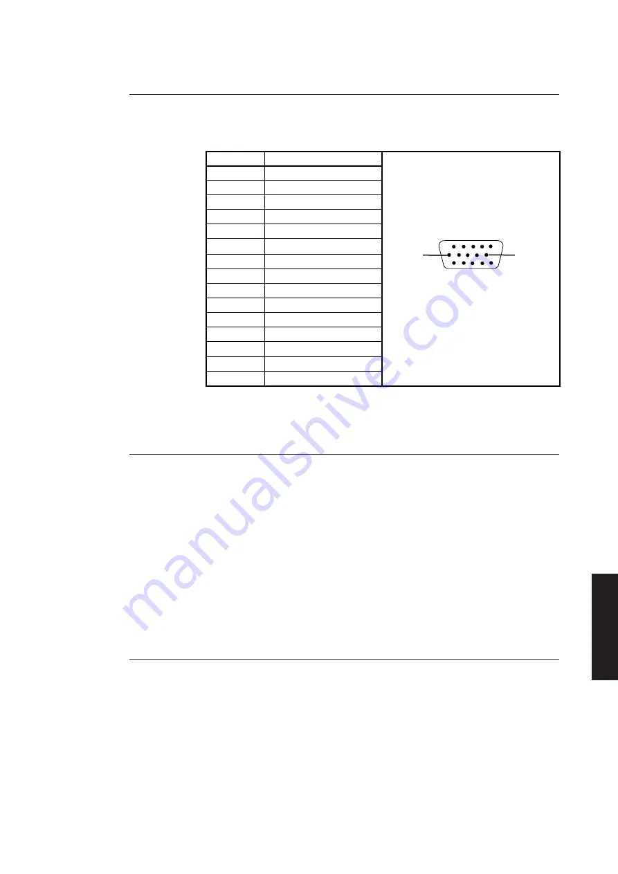
VGA Connector
The monitors are connected to the system board video adapter via a 15 pin D-type
connector. The pinout and details are given below.
Pin
Signal
1
Red
2
Green
3
Blue
4
Reserved
5
Self test
6
Red rtn
7
Green rtn
8
Blue rtn
9
Plug
10
Digital G
11
Reserved
12
Reserved
13
Hsync
14
Vsync
15
Reserved
4.3
HARD DISK DRIVES
Introduction
Four capacities of hard disk drives are available for the Apricot LS Pro range. All the
drives are 1" high, 3.5" form factor using an ATA compatible IDE interface.
The 85,127 and 170 Mbyte drives are from the Quantum ProDrive ELS range, the 213
Mbyte drive is a Maxtor 7213A, the 240 Mbyte drive is a Quantum LPS240A and the
525 Mbyte drive is a Quantum LPS 525A.
Drives connect to the system board hard disk drive connector via a 40-way ribbon
cable. Power is supplied via a separate power connector linked to the system board.
Registers
The system board accesses hard disk drives in I/O space via registers in locations 01F0h
to 01F9h. The function of these registers and their bit significance is given in section 5.
Quantum ProDrive ELS
The 85, 127 and 170 Mbyte hard disk drives that may be fitted in the LS Pro range are
from the Quantum ProDrive ELS range. The drives have nominal access times of 17mS
and can transfer data at up to 4.0 Mbytes per second.
The drive circuit board contains the drive control electronics and a hard disk
controller. A preamplifier for the read/write circuitry and an optical encoder are
located underneath the drive cover.
The drives feature an on-board media defect and error recovery scheme which is fully
user transparent.
Summary of Contents for Apricot LS Pro
Page 1: ...apricot HARDWARE TECHNICAL REFERENCE MITSUBISHI ELECTRIC LS Pro ...
Page 2: ...HARDWARE TECHNICAL REFERENCE ...
Page 6: ...CONTENTS ...
Page 9: ...Chapter 1 INTRODUCTION ...
Page 14: ...Chapter 2 SYSTEM UNIT ...
Page 37: ...Chapter 3 SYSTEM BOARD ...
Page 60: ...Chapter 4 PERIPHERAL ITEMS ...
Page 91: ...Chapter 5 MEMORY AND I O USAGE ...
Page 118: ...Appendix A SPECIFICATIONS ...
Page 125: ...Appendix B REVISION C SYSTEM BOARD ...
Page 130: ...ERROR BEEP CODES Appendix C ...
Page 134: ...INDEX ...


