background image

41

4.

Lift the bay out of the system unit.

5.

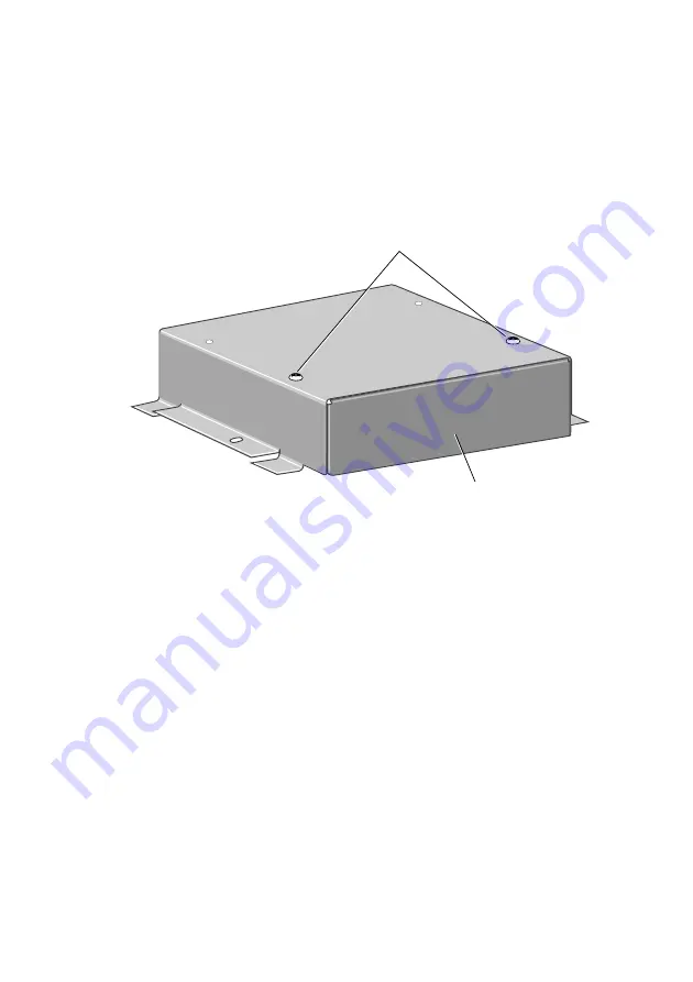
The front of the bay is fitted with a blanking plate.

Turn the bay over and remove the two screws that
secure the blanking plate. The blanking plate is no
longer required, but you may wish to store it
somewhere safe in case you wish to remove the
drive later.

BLANKING PLATE

SECURING SCREWS

6.

Remove the drive from its packaging. With the drive
there should be four screws and a signal cable.
Some drives may be supplied with additional items.

7.

If necessary configure the drive. Drives supplied by
Apricot will be correctly configured for installation in
a XEN-LS II.

For information on how Apricot-supplied drives are
configured see the drive specific information
following these installation instructions.

8.

Identify the top and bottom of the drive.

9.

Rest the drive, top down, on a suitable anti-static
surface.

Summary of Contents for apricot XEN-LS II

Page 1: ...apricot XEN LS II USING SETUP AND INSTALLING ADD ONS MITSUBISHI ELECTRIC ...

Page 2: ...y be used or copied only in accordance with the terms of this agreement It is against the law to copy any disk supplied for any purpose other than the purchaser s personal use All rights reserved no use or disclosure without written consent Copyright Apricot Computers Limited 1992 Published by Apricot Computers Limited 3500 Parkside Birmingham Business Park B37 7YS MITSUBISHI ELECTRIC Printed in t...

Page 3: ...rd 6 System Autoconfiguration 6 Opening screen 7 Change disk types 13 Advanced options 14 Exiting SETUP 20 Installing add ons Introduction 21 Expansion cards 23 Memory 26 Processor upgrades 32 5 25 drives 40 3 5 hard disk drive 48 Appendices A Configuring expansion cards 53 B Video feature connector 64 ...

Page 4: ...2 ...

Page 5: ...ETUP Each time the XEN LS II is switched on or rebooted it runs through a self test procedure During this period the SETUP utility can be invoked by pressing the ALT S key combination The XEN LS II can boot in two ways it can use a graphical boot screen or a conventional text based boot screen During graphical boot a Setup button is displayed SETUP can only be invoked while the button is not greye...

Page 6: ...her Cancel Default Advanced Total Extended 4096KB 3072KB Memory Power on sound High Low Test Enable Power on password Enable Monitor type VGA HiVision 14 Multi sync 14 17 Ethernet interface UTP 10BASE T Thin 10BASE 2 Thick 10BASE 5 Startup Graphics Text Change Message bar Scroll Bar Text Box Button Option group Text Option button Option group These are used to collect a number of related or exclus...

Page 7: ...he SETUP utility displays some information about your system that is detected automatically and cannot be altered For example the amount of memory installed in the system is detected and displayed for information only Buttons Buttons carry out the action indicated by the text on the button Message line A message line at the bottom of the screen contains information about SETUP Greyed out options W...

Page 8: ...nce you are in an option group use the arrow keys to move through the options The system will highlight an entry to show which option is currently selected SPACE BAR Press the space bar to set the highlighted option ENTER Confirms buttons When the changes in a screen are complete are complete select the SAVE button and press ENTER To abandon your changes select the CANCEL button and press ENTER Sy...

Page 9: ... possible inclusion of user defined hard disk drives The Change disk type screen is described in more detail later in this section Boot device The boot device option group allows you to select where you want the XEN LS II to look for an operating system when it is switched on or rebooted The group contains three option buttons these choose between booting from a hard or floppy disk in the computer...

Page 10: ...ace on an expansion card Ethernet If the computer is connected to an Ethernet network using the on board Ethernet interface and it is to boot remotely from a server using the RPL Remote Program Load scheme enable this option Other This option is provided for possible future implementation of other remote boot methods for the on board Ethernet interface It is currently greyed out Memory The memory ...

Page 11: ...character and a maximum length of 7 characters Monitor type There are three option buttons in this group VGA HiVision 14 and Multi sync 14 17 The three options alter the timings of video signals provided by the XEN LS II video connector to suit a variety of different types of monitor It is important to ensure that you have made the correct selection VGA If you have a standard VGA monitor such as t...

Page 12: ... monitor which is compliant with the VESA timings will work with this setting Note This setting must not be chosen for the Apricot HiVision 14 Video modes The XEN LS II motherboard video adapter can generate a wide variety of video outputs In addition to standard VGA modes it supports seven enhanced modes as shown below Resolution Colours Horizontal Vertical Mode Note frequency frequency 640x480 2...

Page 13: ...tion 14 VGA monitor you must select the HiVision 14 option in the monitor type option group In addition to the enhanced modes listed in the table above VGA mode 12 640x480x16 colour also uses the higher vertical frequency when multi sync 14 17 is selected In order to display these enhanced modes correctly you must ensure that the correct monitor type is selected Selecting the wrong monitor type co...

Page 14: ...ct interface If you choose the wrong one you will not be able to use the network connection Advanced This button activates a screen of advanced options Many of the options affect the operation of the motherboard and should only be changed by the technically competent user The operation of the Advanced screen is described in detail later in this section ...

Page 15: ...ays use Autodetect This will ensure that the system uses the correct parameters for the drive The user defined entry is for possible future enhancement to allow non standard drives to be used Floppy 1 and 2 These two option groups allow to select which type of floppy drive is installed Floppy 1 will always be a 3 5 device 1 44M being the standard fitment Floppy 2 if fitted will usually be a 5 25 1...

Page 16: ...ing 10 bit 16 bit Memory hole at 16MB Disable motherboard These check boxes allow you to selectively disable motherboard features You should only disable any of these functions if you are sure it is appropriate Serial port 1 2 Parallel port Checking a box disables the port associated with that box You should only disable a port if you are sure that you do not want to use it Disabling a port in SET...

Page 17: ...rear of this guide Floppy disk controller Checking this box disables the motherboard floppy drive interface Since all XEN LS II systems are supplied fitted with at least one diskette drive you should not normally disable the interface Disabling the floppy drive interface in SETUP disables the relevant motherboard hardware and frees the interrupt and the DMA channel associated with it Information o...

Page 18: ...ems fitted with up to 16 Mbytes of RAM the box can be either checked or unchecked it is unlikely to have a significant effect In systems fitted with more than 16 Mbytes of RAM the box must be checked Memory hole at 16MB This option is used to enable or disable a hole in motherboard memory The hole when enabled appears from 16M 128k to 16M This option should normally be disabled and there is no hol...

Page 19: ...is box disables all three expansion slots This option would not normally be used however under certain circumstances it may be useful For example if you install an expansion card and the computer fails to boot when you power it up You may be able to use this SETUP option to disable the expansion slots and get the computer to boot Motherboard BIOS The system and VGA BIOS on the motherboard is store...

Page 20: ...es performance by copying the contents of the ROM into RAM By copying the BIOS into RAM the system takes advantage of the shorter access times of RAM An additional benefit is that shadowed ROM spaces are cached gaining a further performance advantage Shadow Checking this box enables BIOS shadowing for the associated address range Warning Shadowing is only appropriate for adapter ROM It must never ...

Page 21: ...ard is set to 8MHz the bus is slightly slower than the ISA specification If this option is set to Slow and the switch on the motherboard is set to 10MHz the bus is slightly faster than the ISA specification If this option is set to Fast and the switch on the motherboard is set to 10MHz the bus is significantly faster than the ISA specification I O decoding These two option buttons allow you to cho...

Page 22: ...ced windows The SAVE button will implement any changes that you have made in a screen The CANCEL button exits that screen without implementing any changes Selecting Save or Cancel from the opening screen will exit SETUP If any changes have been made the computer will reboot when you exit SETUP ...

Page 23: ...sh to have your supplier or service organisation install it for you Before you start installing the upgrade you should be thoroughly familiar with all the relevant instructions in this guide and any appropriate sections of your Owner s Handbook Warning Never carry out any work on the equipment with power applied Always switch off at the mains and remove the power lead from the equipment before sta...

Page 24: ...e major components inside the XEN LS II system unit that are affected by the installation instructions later in this section BLANKING PLATES EXPANSION CARD CONNECTORS CARD GUIDES BRACE SIMM SOCKETS 5 25 DRIVE BAY POWER SUPPLY 3 5 DRIVE BAY PROCESSOR UPGRADE SOCKET ...

Page 25: ...equence 1 Power the system down 2 Take suitable anti static precautions and remove the system unit cover If you are unfamiliar with Apricot s recommended anti static precautions and or the process of removing the system unit cover refer to either the appendices at the rear of this guide or your Owner s Handbook 3 With the system unit cover removed the space for expansion cards will be visible It i...

Page 26: ...ve bay then it is easiest to install it in the top slot Warning The video feature connector on the XEN LS II motherboard uses a non standard pinout In order to use the connector you will need to make up a special cable A pinout of the XEN LS II video feature connector is given in the Appendix B at the rear of this guide To remove the blanking plate first unscrew the securing screw then slide the p...

Page 27: ...feature connector on the motherboard you must plug the video feature cable into the motherboard socket before you install the card 7 Slide the card into the slot ensuring that the card edge connector engages correctly with the expansion card connector 8 Carefully push the card fully home Do not apply excessive pressure 9 Secure the card by replacing the screw that you removed in step 4 10 Connect ...

Page 28: ...sible memory capacities using the various SIMM combinations MM1 MM2 Upgrade Motherboard Available capacity capacity capacity memory memory 4 4 4 4 4 8 8 8 4 12 16 16 4 20 32 32 4 36 4 4 8 4 12 4 8 12 4 16 4 16 20 4 24 8 8 16 4 20 8 16 24 4 28 16 16 32 4 36 32 4 36 4 40 32 8 40 4 44 32 16 48 4 52 32 32 64 4 64 Note When a 32Mbyte SIMM is installed in MM2 the motherboard memory is disabled It should...

Page 29: ...2Mbyte SIMM it should always go in MM1 unless there is a 32Mbyte SIMM in the socket already If in either of the cases above you install a 4 or 32 Mbyte in MM2 when you power the system up you will be prompted to swap the SIMMs Installation In order to install a memory upgrade you must 1 Power the system down 2 Take suitable anti static precautions and remove the system unit cover If you are unfami...

Page 30: ...must remove the 5 25 drive bay SECURING SCREWS 5 25 BAY 3 If there is a drive fitted disconnect the power and signal cables from the rear of the drive 4 Remove the two screws that secure the drive bay and slide the bay backwards 5 Lift the bay out of the system unit and put it down on a safe flat surface ...

Page 31: ... side of the socket gently away from the SIMM using your forefingers 2 Place your thumbs on the top edge of the SIMM and move it gently towards the vertical 3 When the SIMM has rotated through 20 taking care to avoid touching any of the components on the SIMM grip the top corners of the SIMM between thumb and first finger and carefully pull the SIMM out of the socket ...

Page 32: ...stall in one orientation There is a cutout at one end of the SIMM next to the connector strip Hold the SIMM with the cutout on the right and metal connector strip nearest the motherboard 2 Position the SIMM above the socket with the SIMM tilted slightly towards the front of the system unit 3 Lower the SIMM into the socket and ensure that the SIMM is properly located in the connector ...

Page 33: ... want to install a second SIMM repeat the process above Once you have completed installation you can replace the 5 25 drive bay and reassemble the system 1 Replace the 5 25 bay in the system unit 2 Slide the bay forwards until the two holes in the bay line up with those in the hard drive assembly and the system unit brace 3 Replace the two screws which secure the 5 25 drive bay 4 If there is a dri...

Page 34: ...erDrive 25 OverDrive 33 Intel486DX 33 OverDrive 25 OverDrive 33 Note This table lists the processors supported by the motherboard There is no guarantee that any particular upgrade processor will be available at any given time Depending on the processor type fitted in your system unit the processor socket may already be occupied Before installing the upgrade processor you must first check whether t...

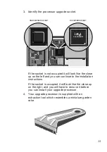
Page 35: ...ook like the close up on the left and you can continue to the installation instructions If the socket is occupied it will look like the close up on the right and you will have to remove it before you can install your upgrade processor 4 Your upgrade processor is supplied with an extraction tool which resembles a miniature garden rake ...

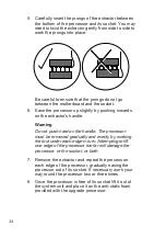
Page 36: ... Do not push hard on the handle The processor must be removed gradually and evenly by working the tool under each edge in turn Attempting to lift one edge of the processor too far will damage the processor or the socket or both 7 Remove the extractor and repeat the process on each edge of the processor gradually easing the processor out of its socket If necessary work your way round the processor ...

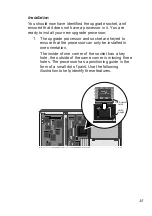
Page 37: ...essor and socket are keyed to ensure that the processor can only be installed in oneorientation The inside of one corner of the socket has a key hole the outside of the same corner is missing three holes The processor has a positioning guide in the form of a small dot of paint Use the following illustration to help identify these features POSITIONING GUIDE KEYED CORNER int l e OVERDRIVE ...

Page 38: ... processor or the socket or both 3 Gently insert the upgrade processor making sure that it is correctly aligned with the socket and that you do not bend or otherwise damage the pins 4 Once you are certain that all the pins on the processor are in the holes in the socket apply firm even pressure to the top of the processor to seat the pins in the socket 5 With the upgrade processor installed you mu...

Page 39: ... the upgrade socket configuration are set correctly Follow the instructions below to check the settings and adjust them as necessary 1 Use the following illustration to identify the switches ON 1 2 3 4 5 6 SWITCH PACK int l e OVERDRIVE The switches numbered 2 and 3 are used to select the system clock speed Switches 4 and 5 are used to configure the upgrade socket Warning Under no circumstances sho...

Page 40: ...eplacement on off Intel486SX on on not used 3 Having decided which selection you require check the positions of switches 4 and 5 and if necessary move them to the appropriate position The easiest way to move the switches is with the point of a pencil or small screwdriver 4 From the table below and the label on your upgrade processor or its packaging decide which system clock speed you need to sele...

Page 41: ...positions of switches 2 and 3 and if necessary move them to the appropriate position The easiest way to move the switches is with the point of a pencil or a small screwdriver 6 You should by now have identified the upgrade socket and if necessary removed the processor fitted in it installed the new processor configured the upgrade socket and set the system clock speed If you are uncertain about ha...

Page 42: ...y to all drives and describe the physical installation of a drive Instructions specific to each drive type are given after the generic instructions Generic 1 Power the system down 2 Take suitable anti static precautions and remove the system unit cover If you are unfamiliar with Apricot s recommended anti static precautions and or the process of removing the system unit cover refer to your Owner s...

Page 43: ...G SCREWS 6 Remove the drive from its packaging With the drive there should be four screws and a signal cable Some drives may be supplied with additional items 7 If necessary configure the drive Drives supplied by Apricot will be correctly configured for installation in a XEN LS II For information on how Apricot supplied drives are configured see the drive specific information following these insta...

Page 44: ...42 10 With the drive bay upside down place it over the drive The front of the drive must be at the end where the blanking plate was fitted COMPACT SECURING SCREW HOLES ...

Page 45: ...ive securing screws and tighten them until they are finger tight 13 Gently tighten the four screws 14 Turn the drive bay over and replace it in the system unit 15 Slide the bay forwards until the two holes in the bay line up with those in the hard drive assembly and the system unit brace 16 Replace the two screws that secure the drive bay ...

Page 46: ...to the power connector on the drive 5 25 DRIVE POWER CABLE int l e OVERDRIVE 18 The drive has now been installed and connected to a power cable You must now connect it to a signal cable Instructions on connecting each of the types of drive to a signal cable is given under the appropriate heading overleaf ...

Page 47: ...se drives is via the drive select jumpers at the rear of the drive The jumpers should be set to drive select 1 DS1 SLCD CD ROM Cabling The Apricot SLCD CD ROM drive is supplied with two signal cables The wide data cable must be connected between the rear of the SLCD CD ROM drive and PL36 on the motherboard The narrow audio cable must be connected between the drive and PL4 on the motherboard Use th...

Page 48: ...ette supplied with the drive SCSI drives Cabling Apricot upgrade kits are supplied with a suitable signal cable The cable should be connected between the SCSI card and the rear of the drive The connector at the drive end should be fitted with a termination assembly The following illustration shows the routing of the cable 486 int l e DX i TM SCSI CABLE ...

Page 49: ... known as SCSI IDs All Apricot SCSI drives for XEN LS II are supplied configured with SCSI ID 2 All Apricot SCSI drives are supplied without termination SCSI bus termination is provided by the SCSI card and the termination assembly in the last connector at the drive end of the cable ...

Page 50: ...move it 3 Take suitable anti static precautions and remove the system unit cover If you are unfamiliar with Apricot s recommended anti static precautions and or the process of removing the system unit cover refer to your Owner s Handbook In order to remove the 3 5 drive bay you must first remove the 5 25 drive bay SECURING SCREWS 5 25 BAY 4 If there is a drive fitted in the 5 25 bay disconnect the...

Page 51: ...oppy drive 8 If a 3 5 hard disk is fitted remove the signal and power cables from the rear of the drive 9 The 3 5 drive bay is secured by two screws and two lugs in the system unit base Identify the screws and lugs from the following illustration 486 int l e DX i TM SECURING SCREWS 10 Remove the two securing screws shown in the illustration above 11 Slide the 3 5 drive bay backwards and lift it ou...

Page 52: ...r and Slave A single drive or the boot device in a dual drive system must be configured as Master The second non bootable drive in a dual drive system must be configured as Slave IDE drives are normally configured using jumpers on the drive Configuration details may vary from drive to drive Apricot drives are supplied with documentation describing how to configure the drive If you are uncertain ab...

Page 53: ...touch it Warning It is possible to damage hard disk drives when attaching them using side mounting holes When installing Apricot supplied hard disk drives make sure that you use the screws supplied with the drive and that all washers supplied are used When installing drives supplied by third parties be careful to ensure that securing screws do not come into contact with drive circuit boards If in ...

Page 54: ...e front bezel and the two screw holes in the bay line up with those in the base of the system unit 3 Replace the two securing screws 4 Connect the 3 5 hard disk s to their signal and power cables 5 Reconnect the 3 5 floppy drive cable Warning If the 3 5 floppy drive cable has been disconnected from the system board make sure that you reconnect it to the correct connector Check the label on the ins...

Page 55: ...sks supplied with the card for README or Help files Most ISA cards use jumpers and or switches to select their configuration options If this is the case then the card should be configured before you install it A few cards are configured using a software utility supplied with the card this can only be done after the card is installed If you are not familiar with the concepts of interrupts DMA chann...

Page 56: ...literally interrupted A hardware interrupt may be referred to as an IRQ This is because the motherboard signals used to generate the interrupts are labelled IRQx where x is a number between 0 and 15 excluding 2 Note In an ISA compatible system if you select IRQ2 on an expansion card it uses IRQ9 This means that if an expansion card is using IRQ2 no other card can use IRQ9 Some interrupts are assig...

Page 57: ...is available for an expansion card IRQ10 INA The Ethernet interface can be disabled using SETUP if you Ethernet are not using the on board Ethernet adapter to connect to a network In this case IRQ10 is available for an expansion card IRQ15 Audio The audio system can be disabled using SETUP if you are not using it In this case IRQ15 is available for an expansion card IRQ14 Hard disk The hard disk c...

Page 58: ...ction can be disabled if so how and under what circumstances it is safe to do so DMA Function Note channel 0 SLCD Available if no SLCD CD ROM CD ROM drive is fitted and the SLCD interface is interface disabled in SETUP 1 Audio Available if the audio system is disabled in SETUP channel A 2 Floppy drive Always used by the interface motherboard 3 Audio Available if the audio system is disabled in SET...

Page 59: ...Numbers and computers For a variety of reasons in computer literature and terminology numbers are sometimes in hexadecimal notation rather than the decimal that we are all familiar with Hexadecimal is a long word and it is often shortened to hex If you think of the decimal system using columns 1000 100 10 1 10x10x10 10x10 10 1 The number 1019 is 1000 100 10 1 1 0 1 9 Each time you add 1 to a colum...

Page 60: ...096x0 256x3 16xF 1xB 768 240 11 1019 Note A lower case h is often used at the end of a number to ensure that you realise it is in hex format e g 3FBh A larger hex number and one that you will come across in the Memory map description below is A0000h To see this as a decimal number 16x16x16x16 16x16x16 16x16 16 1 A 0 0 0 0 16x16x16x16 65536 So A0000h is 65536x10 655360 If you have Microsoft Windows...

Page 61: ...e The processor s address space can be thought of as a list of locations the locations are each identified by a number The first or bottom location is address 0 Every address contains 8 bits of data a byte Each bit can be thought of as a switch which can be either on or off A byte is like a bank of 8 switches where each switch can be on or off ON 1 2 3 4 5 6 7 8 OFF BYTE ON 1 OFF BIT So 1Mbyte of ...

Page 62: ...BIOS SETUP OPTION ROM EXPANSION CARD ROM VIDEO BIOS VIDEO MEMORY DOS 1M 1 960K 896K 800K 768K 640K FFFFFh F0000h E0000h C8000h C0000h A0000h 00000h 0 Note The top location of this first Mbyte is 1M 1 or FFFFFh This is because in the first Mbyte there are 1M locations starting at 0 Location 1M is the start of the second Mbyte of address space The memory map above shows the uses of the first Mbyte o...

Page 63: ...o FFFFFh is used by the motherboard BIOS When installing expansion cards the area of most interest is between 768k and 896k 1 C0000h to DFFFFh Configuring expansion ROM Expansion card ROM is addressed in the C0000h to DFFFFh region of processor address space On the XEN LS II motherboard video BIOS is accessed from C0000h to C7FFFh If you are installing a video card it should be configured with its...

Page 64: ... be selected on the card Refer to the following table and the documentation supplied with the card to establish which ports if any to use and how to select them Free I O ports Hex 100 11F 128 1EF 202 2F7 324 387 390 3B3 3B6 3B9 3D0 3D3 3D6 3D9 3DB 3EF 400 51F 528 917 928 FFFF Note 1 I O ports are always given in hex notation If you are unfamiliar with this notation refer to Numbers and computers e...

Page 65: ...63 Expansion Card Configuration IRQ DMA channel ROM address I O ports Card Slot 1 2 3 ...

Page 66: ...ill have to make up a special cable The pinout of the motherboard connector is given in the following table Pin Function Pin Function 1 Ground 2 P7 3 Ground 4 P6 5 Ground 6 P5 7 EVIDEO 8 P4 9 ESYNC 10 P3 11 EDCLK 12 P2 13 No connect 14 P1 15 Ground 16 P0 17 Ground 18 DCLK 19 Ground 20 BLNK 21 Ground 22 HSYNC 23 Ground 24 VSYNC 25 Ground 26 Ground 2 1 26 25 ...

Page 67: ...apricot MITSUBISHI ELECTRIC APRICOT COMPUTERS LIMITED 3500 PARKSIDE BIRMINGHAM BUSINESS PARK BIRMINGHAM B37 7YS Part No 15028131 Revision No 02 ...

Reviews: