


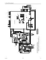


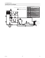


[
VI
Refrigerant Circuit ]
- 59 -
HWE10060
GB
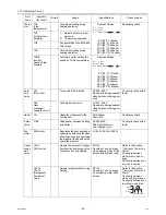
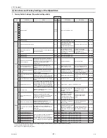
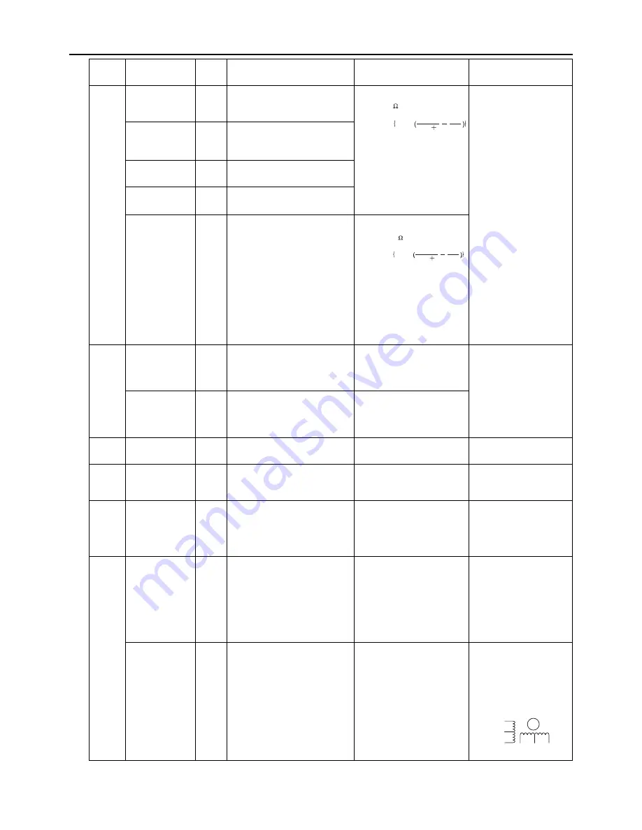
Thermi
stor
TH3
(Pipe
temperature)
Controls defrosting during
heating operation
Degrees Celsius
0°C[32°F] :15kohm
10°C[50°F] :9.7kohm
20°C[68°F] :6.5kohm
25°C[77°F] :5.3kohm
30°C[86°F] :4.4kohm
40°C[104°F] :3.0kohm
Resistance check
TH7
(Outdoor tem-
perature)
1) Detects outdoor air tem-
perature
2) Controls fan operation
TH5
Fan operated on the 63LS and
TH5 values.
TH6 Controls
defrosting
during
heating operation
THHS
Inverter
heat sink tem-
perature
Controls inverter cooling fan
based on THHS temperature
Degrees Celsius
0°C[32°F] :161kohm
10°C[50°F] :97kohm
20°C[68°F] :60kohm
25°C[77°F] :48kohm
30°C[86°F] :39kohm
40°C[104°F] :25kohm
Sole-
noid
valve
SV1
INJ control
Turns on/off the injection
AC220 - 240V
Open while being powered/
closed while not being pow-
ered
Continuity check with a
tester
SV2
Heat
exchanger
capacity control
Controls defrost cycle
AC220 - 240V
Open while being powered/
closed while not being pow-
ered
Heater CH
Heats the refrigerant in the
compressor
Cord heater
ohm 45W
Resistance check
4-way
valve
21S4
Changeover between heating
and defrost
AC220-240V
Dead: defrost cycle
Live: heating cycle
Continuity check with a
tester
Fan
motor
FAN motor
Regulates the heat exchanger
capacity by adjusting the oper-
ating frequency and operating
the propeller fan based on the
operating pressure.
AC342V, 50.5Hz, 920W
Linear
expan-
sion
valve
LEV2
(INJ control)
Adjusts the amount of bypass
flow from the liquid pipe on the
outdoor unit during heating
DC12V
Opening of a valve driven
by a stepping motor 0-480
pulses (direct driven type)
Refer to the section
"Continuity Test with a
Tester".
Continuity between
white, brown, and or-
ange.
Continuity between yel-
low, red, and blue.
LEV1a
LEV1b
(Refrigerant
flow adjust-
ment)
Adjusts refrigerant flow during
heating
DC12V
Opening of a valve driven
by a stepping motor 2000
pulses
Refer to the section
"Continuity Test with a
Tester".
Continuity between
white, red, and orange.
Continuity between yel-
low, brown, and blue.
Part
name
Symbols
(functions)
Notes
Usage
Specifications
Check method
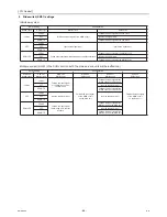
R = 15k
0
R = 3385
R = 15
0/80
t
3385 273 t
1
273
1
exp
R = 17k
50
R = 4016
R = 17
25/120
t
4016
273 t
1
323
1
exp
Yellow
White
Red
Orange
Brown Blue
M
Summary of Contents for CAHV-P500YA-HPB
Page 1: ...Service Handbook Service Handbook CAHV P500YA HPB Model 2011 HOT WATER HEAT PUMP ...
Page 7: ...CONTENTS HWE10060 GB ...
Page 9: ... 2 HWE10060 GB ...
Page 19: ... 12 HWE10060 GB ...
Page 37: ... 30 HWE10060 GB ...
Page 46: ... 39 HWE10060 GB IV Remote Controller 1 Using the Remote Controller 41 2 Function Settings 46 ...
Page 47: ... 40 HWE10060 GB ...
Page 55: ... IV Remote Controller 48 HWE10060 GB ...
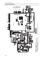
Page 56: ... 49 HWE10060 GB V Electrical Wiring Diagram 1 Electrical Wiring Diagram 51 ...
Page 57: ... 50 HWE10060 GB ...
Page 61: ... V Electrical Wiring Diagram 54 HWE10060 GB ...
Page 63: ... 56 HWE10060 GB ...
Page 67: ... VI Refrigerant Circuit 60 HWE10060 GB ...
Page 69: ... 62 HWE10060 GB ...
Page 101: ... VII Control 94 HWE10060 GB ...
Page 103: ... 96 HWE10060 GB ...
Page 109: ... VIII Test Run Mode 102 HWE10060 GB ...
Page 111: ... 104 HWE10060 GB ...
Page 155: ... IX Troubleshooting 148 HWE10060 GB ...
Page 156: ... 149 HWE10060 GB X Attachments 1 R407C saturation temperature table 151 ...
Page 157: ... 150 HWE10060 GB ...
Page 159: ... X Attachments 152 HWE10060 GB ...


