


[
VII
Control ]
- 82 -
HWE10060
GB
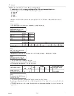
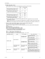
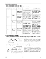
Bypass Control
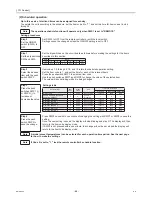
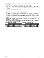
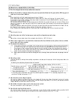
-5- Outdoor unit fan
The fan's rotation speed will be controlled to approximate the values in the table below that are obtained based on the outside
temperature and the low pressure.
(Pressures and temperatures will be monitored, and the fan frequency will change accordingly in three steps.)
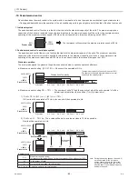
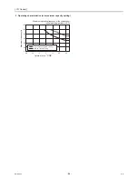
Compressor Frequency Control
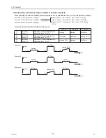
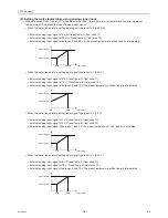
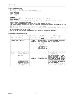
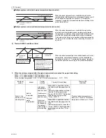
-6- Injection LEV
Operating range of the LEV
Opening range: 50-480 (fully open)
LEV operation speed
Open 133 plus/sec
Close 200 plus/sec
At startup
For one minute after startup, the valve will be fixed to Initial Setting 1.
Between one and five minutes after startup, the valve will be fixed to Initial Setting 2.
During operation
Five or more minutes after startup, LEV2 (Injection LEV) opening will be controlled every 30 seconds to approximate the dis-
charge SH to the target value according to the changes in high pressure and discharge gas temperature.
(Refer to the table below for the target discharge SH values.)
Fan rotation
speed (rpm)
Frequency (Hz)
Outdoor temp.(A)
(°C)
Fan rotation
speed (rpm)
Frequency
(Hz)
Outdoor temp.(A)
(°C)
270
31
37 < A
≤
40
450
50
12 < A
≤
17
300
34
32 < A
≤
37
490
55
7 < A
≤
12
330
37
27 < A
≤
32
550
60
2 < A
≤
7
370
41
22 < A
≤
27
600
66
0 < A
≤
2
410
45
17 < A
≤
22
670
73
A
≤
0
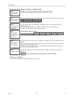
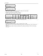
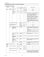
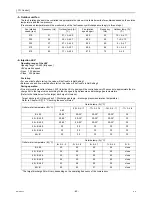
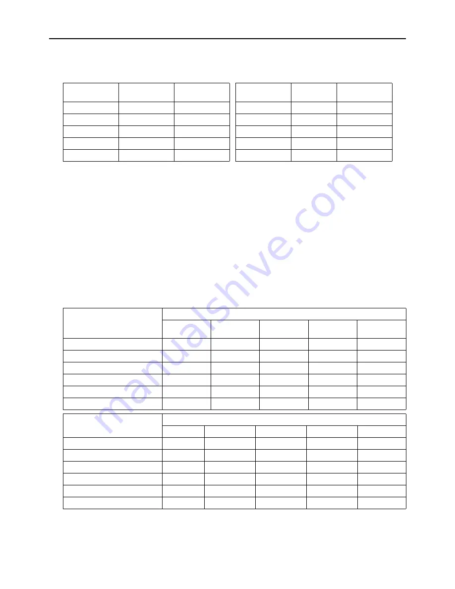
Target discharge SH (Item code c31: Discharge gas temp. - discharge pressure saturation temperature)
Refer to Chapter IX [1] 2. "Checking the sensor status."
Outlet water temperature (B) (°C)
Outside temp.(A) (°C)
≤
-20
-20< A
≤
-17
-17< A
≤
-14
-14< A
≤
-11
-11< A
≤
-8
B
≤
45
20-35*
20-35*
20-35*
20-35*
35
45 < B
≤
50
20-30*
20-30*
20-30*
20-30*
30
50 < B
≤
55
20-25*
20-25*
20-25*
20-25*
25
55 < B
≤
60
20
20
20
20
20
60 < B
≤
65
20
20
20
20
20
65 < B
20
20
20
20
20
Outlet water temperature (B) (°C)
Outside temp.(A) (°C)
-8< A
≤
-5
-5< A
≤
-2
-2< A
≤
1
1< A
≤
5
5< A
B
≤
45
40
45
50
55
close
45 < B
≤
50
35
40
45
50
close
50 < B
≤
55
30
35
40
45
close
55 < B
≤
60
25
30
35
40
close
60 < B
≤
65
23
26
30
35
close
65 < B
20
23
27
32
close
*The target discharge SH will vary, depending on the operating frequency of the compressor.
Summary of Contents for CAHV-P500YA-HPB
Page 1: ...Service Handbook Service Handbook CAHV P500YA HPB Model 2011 HOT WATER HEAT PUMP ...
Page 7: ...CONTENTS HWE10060 GB ...
Page 9: ... 2 HWE10060 GB ...
Page 19: ... 12 HWE10060 GB ...
Page 37: ... 30 HWE10060 GB ...
Page 46: ... 39 HWE10060 GB IV Remote Controller 1 Using the Remote Controller 41 2 Function Settings 46 ...
Page 47: ... 40 HWE10060 GB ...
Page 55: ... IV Remote Controller 48 HWE10060 GB ...
Page 56: ... 49 HWE10060 GB V Electrical Wiring Diagram 1 Electrical Wiring Diagram 51 ...
Page 57: ... 50 HWE10060 GB ...
Page 61: ... V Electrical Wiring Diagram 54 HWE10060 GB ...
Page 63: ... 56 HWE10060 GB ...
Page 67: ... VI Refrigerant Circuit 60 HWE10060 GB ...
Page 69: ... 62 HWE10060 GB ...
Page 101: ... VII Control 94 HWE10060 GB ...
Page 103: ... 96 HWE10060 GB ...
Page 109: ... VIII Test Run Mode 102 HWE10060 GB ...
Page 111: ... 104 HWE10060 GB ...
Page 155: ... IX Troubleshooting 148 HWE10060 GB ...
Page 156: ... 149 HWE10060 GB X Attachments 1 R407C saturation temperature table 151 ...
Page 157: ... 150 HWE10060 GB ...
Page 159: ... X Attachments 152 HWE10060 GB ...


