PCKN-OIL738
13
4.2 Measurement
Voltages input to the relay are measured and converted into freely set VT primary voltages, then indicated
in the display.
(1) Real time measurement
The effective voltage input to the relay under steady state is displayed.
(2) Max.
record
The maximum effective voltage is recorded and stored.
The max. record will be all cleared when “aux. power supply OFF” or “max. record reset” operation is
made.
(3) Fault
record
In the event of system fault, the effective voltage and waveform data that have been measured at the
time when one of the protection elements operates to issue an output signal are stored. Data of up to
five phenomena can be stored and displayed for each phase.
With “aux. power supply OFF”, only the waveform data will be cleared and the effective voltage data
will remain. With “fault record reset” operation, however, both of the data items will be all cleared.
(Records older than the 5
th
phenomenon will automatically be cleared.)
Item No.
History
Sequence of recording
211 1
st
phenomena
212 2
nd
phenomena
213 3
rd
phenomena
214 4
th
phenomena
215 5
th
phenomena
Latest fault record data
↓
↓
↓
Oldest fault record data
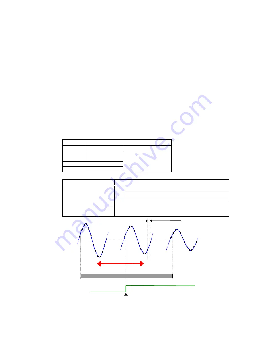
The following fault waveform data can be collected if a communication card is installed:
Item Specification
Data sampling cycle
Fixed to the electric angle of 30° of rated frequency
Data storing capacity (for
a phenomenon)
224 cycles of rated frequency
(Data point: 224×360°/30° = 2688 points)
Permissible setting range
224 cycles before trip ~ 224 cycles after trip
Collected data
The range for data collection can be set by cycle within the
“data storing capacity” in the “permissible set range”.
224 cycles after trip
→
←
224 cycles before trip
Collected data
Up to 224 cycles
Data sampling cycle
Trip occurs!
Output contact
ON
OFF
Permissible set
Figure 4.4 Concept of recording fault waveform


