PCKN-OIL738
23
Self-diagnosis
output
Trip
DA
DB
SLD
DG
B-06
B-05
B-07
B-08
B-09
B-10
B-11
B-12
B-13
B-14
B-17
B-18
B-19
B-20
B-01
B-02
B-03
B-04
Serial communication
bus
E
A-02
+
Auxiliary
power
supply
A-01
A-03
Programmable
output
Signaling
U>
Ov
ervolta
ge
U<
Undervoltage
Y
X
0
X
1
X
3
X
4
X
5
X
2
CPS1 type
AC/DC
converter
or
UPS
To control
system (alarm
and other
signals)
52a
Time-delayed
operation
contact
(make contact)
Approx. 1 s
100VDC ~ 220VDC
100VAC ~ 220VAC
TL
TC
To master
station (when
communication
card installed)
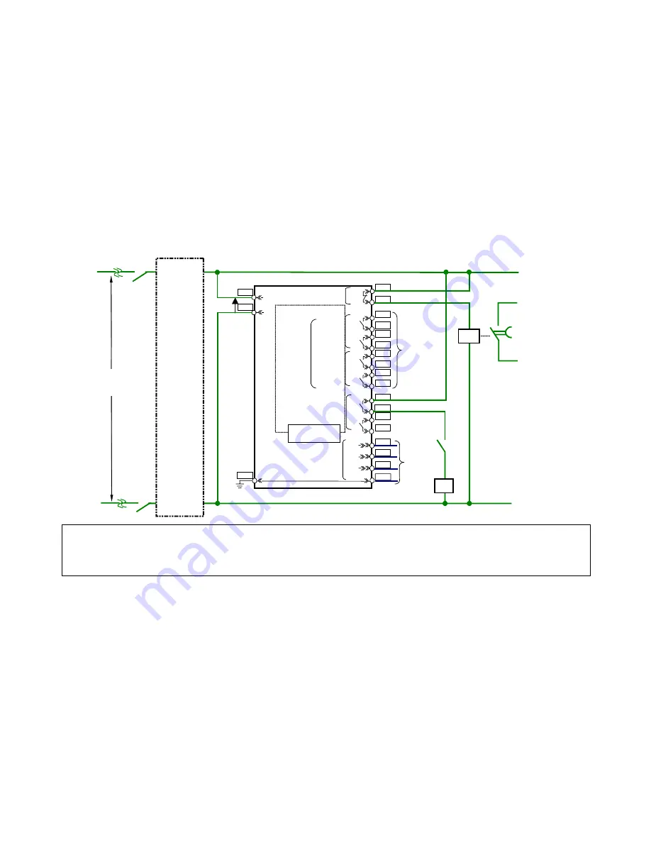
Note 1) The self-diagnosis output contact is so configured that the auxiliary relay can be energized (“break contact” opened) when normal result of self-diagnosis is received.
This type of contact will allow the relay to continue automatic self-check even after the built-in power fuse burns. Therefore, the “break contact” is closed when the power
is applied and will be opened after about 50ms. If the auxiliary power supply of the relay and the self-diagnosis output contact shares a same power source,
the “break
contact” will be closed temporarily after the auxiliary power supply is turned on
. In the case where the phenomenon stated in the above would conflict with your
system requirement, it is recommended that the self-diagnosis output contact should be
connected via the time-delayed timer
as shown in the left of the figure.
Note 2) Regarding to the type CPS1 AC/DC converter or commercially available uninterruptible power supply (UPS), refer to the note *21 in the section 2.1 General information.
Figure 5.6 Auxiliary power supply circuit connection example of type CBV2-A01D1 relay


