5 - 2 5 - 2
MELSEC-A
5 HANDLING CC-LINK EMBEDDED I/O ADAPTER
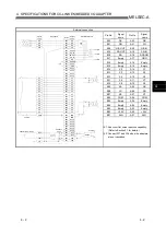
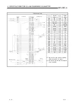
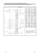
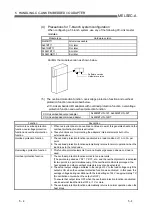
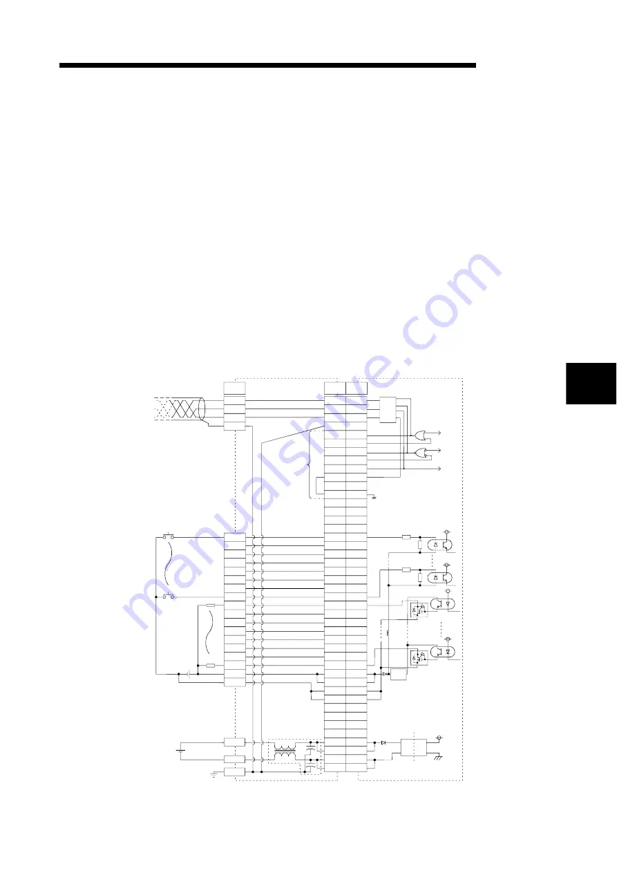
(2) Precautions for external wiring
Note the following when designing the user board side circuit and board patterns.
1) Use a user board of 1.6mm thickness.
2) When the noise immunity must be increased, insert a noise filter (FDK
make: NFR5UI203MB or equivalent) and Y capacitor (22000pF 630V) in the
adapter power supply line.
3) Connect the transmission SLD and FG within the board.
As a pattern, connect SLD and FG as near as possible to the external I/O
terminals.
4) Make the transmission patterns (DA, DB) as short as possible.
Design the patterns so that the capacitance is 20pF or less with the CC-Link
embedded I/O adapter mounted on the board. (Guidelines: Pattern length
5cm or less, pattern width 0.18mm or less)
5) Since the cascade communication signal pins (16-point adapter: A17 to A20
pins and B17 to B20 pins, 32-point adapter: A26 to A29 pins and B26 to B29
pins) are susceptible to noise, keep them as far away as possible from the
other patterns (power supply, I/O signal) that include noise.
6) When the adapters are not cascaded, always connect GND and RDGON
(16-point adapter: A17 pin and A18 pin, 32-point adapter: A26 pin and A27
pin) on the board side.
7) Wire the FG pattern so that it does not cross the I/O patterns on the front
and back sides of the board.
Doing so makes the adapter sensitive to noise.
(Example: AJ65MBTL1N-16DT)
Link
IC
AJ65MBTL1N-16DT
User board
Signal
name
Singnal
name
Pin No.
B22
A22
B21
A21
B20
A20
B19
A19
B18
A18
B17
A17
B16
A16
B15
A15
B14
A14
B13
A13
B12
A12
B11
A11
B10
A10
B09
A09
B08
A08
B07
A07
B06
A06
B05
A05
B04
A04
B03
22000pF
630V
A03
B02
A02
B01
A01
DA
DA
DB
DG
SLD
DB
DG
FG
OE-OUT
OE-IN
SD-OUT
SD-IN
RD
RDGON
GND
X0
X1
X2
X3
X4
X5
X6
R
R
X7
Y8
Y9
YA
YB
YC
YD
YE
YF
24V DC
24V DC
24G DC
24G DC
+24V
DC/DC
+24V
+24V
24G
FG
24G
24G
X0
X1
X2
X3
X4
X5
X6
X7
Y8
Y9
YA
YB
YC
YD
YE
YF
L
L
24V DC
24V DC
24G DC
R
R
4)
6)
7)
2)
3)
Adapter power supply
Insulation
Constant
voltage
circuit
To G/A
To G/A
To G/A
1)
5)
Empty
Empty
Empty
Empty
Empty
Empty
Empty
Empty
Empty
5
Summary of Contents for CC-Link
Page 1: ...CC Link Embedded I O Adapter User s Manual ...
Page 2: ......
Page 13: ...1 5 1 5 MELSEC A 1 OVERVIEW MEMO ...
Page 17: ...3 2 3 2 MELSEC A 3 SPECIFICATIONS MEMO 3 ...
Page 43: ......


