WT05688X01
4. Insulation Cover Installation
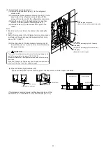
Install the insulation cover on the twinning kit after brazing the pipes and twinning kit.
Insulate all refrigerant pipes. Insulate the high-pressure and low-pressure pipes separately, and pipes located inside the unit as well as
the outside. Use heat-resistant insulation material (Heat resistant : at least 120˚C [248˚F], Thickness: high-pressure = 10 mm [13/32 in.],
low-pressure = 20 mm [13/16 in.] ). Position the edges of the insulation cover and heat-resistant insulation material so as not to leave a
gap, and then wrap the exterior perimeter of the pipe joints and middle with tape (field-supplied).
Tape (field-supplied)
Overlap margin of the tape
Insulation cover
Heat-resistant insulation material (field-supplied)
Insulation covers can shrink.
Overlap the tape as shown in the left
figure so that there will be no gap in-
between the insulation cover or
field-installed insulation material.
field-supplied pipe
Heat-resistant insulation material (field-supplied)
Heat-resistant insulation material (field-supplied)
field-supplied pipe
field-supplied pipe
2
High-pressure
twinning pipe
B
Insulation cover
Tape (field-supplied)
To be gap free
To be gap free
4
See reverse.
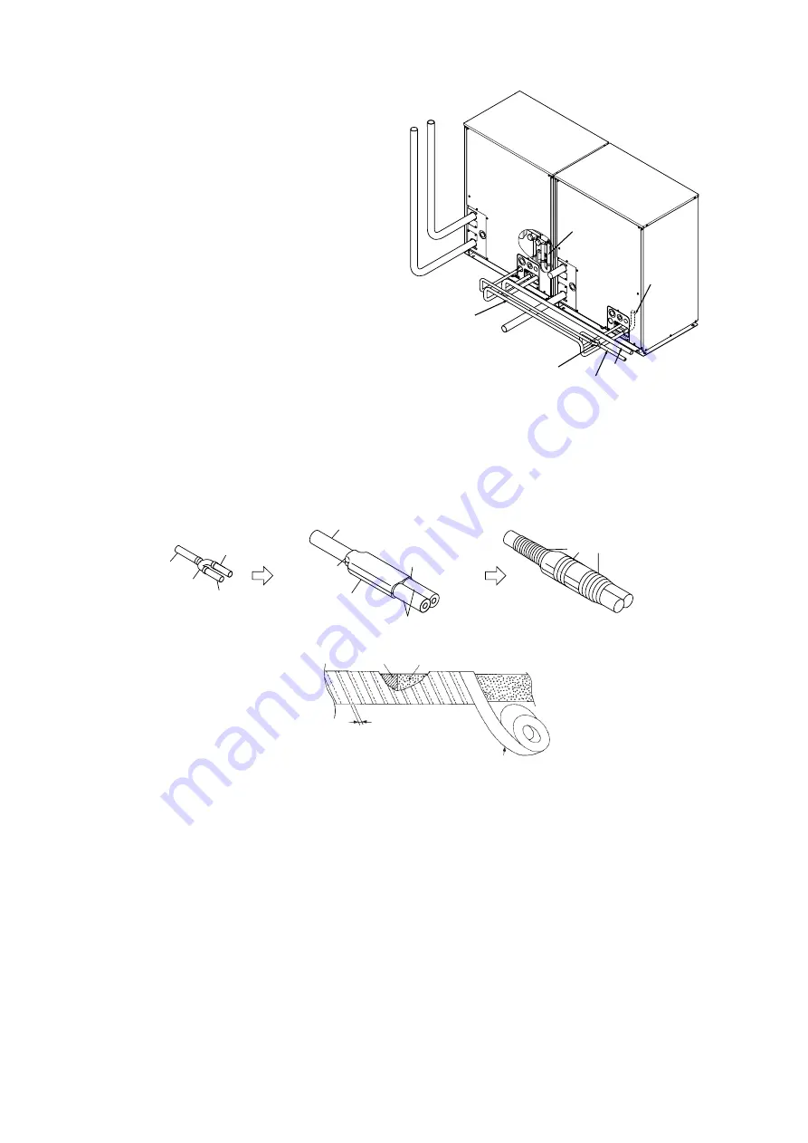
3. Pipe Connection Example
Connect the pipes between heat source units,
referencing the figure below.
1
Low-pressure
twinning kit
Low-pressure connecting pipe
(Between heat source units)
2
High-pressure twinning pipe
Main high-pressure pipe (To BC controller)
Main low-pressure pipe (To BC controller)
D
ID22.2 [7/8]
-ID25.4 [1]
5. Miscellaneous Notes
Secure the field-supplied pipes with a pipe cover and a cable tie in place to keep them from coming in contact with other pipes as
necessary.
Install the insulation cover so that the edges of the cover meet at the top.


