[
IV
Outlines and Dimensions ]
- 15 -
HWE19070
GB
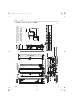
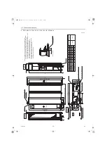
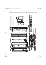
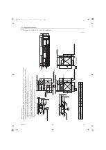
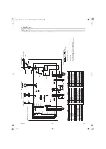
2. PEFY-M20, 25, 32, 40, 50, 63, 71, 80, 100, 125, 140VMAL-A
Unit: mm
Control box
2×2-ø2.9
Air
outlet
Air
inlet
2×E-ø2.9
Refrigerant piping
Brazing connection (liquid)
2
1
Refrigerant piping
Brazing connection (gas)
Air Filter
T
e
rminal block (Power source)
T
e
rminal block (T
ransmission)
Drain pipe (O.D.ø32)
Suspension bolt hole
4-14×30 Slot
<Accessory>
Drain hose (I.D.
ø
32)
(Actual length)
Note 1.Use M10 screw for the Suspension bolt (field supply).
2.Keep the service space for the maintenance at the bottom.
3.This chart indicates for PEFY
-M71·80VMAL-A
models,
which have 2 fans.PEFY
-M20·25·32VMAL-A
models have 1 fan.
PEFY
-M40·50·63VMAL-A
models have 2 fans.
PEFY
-M100·125·140VMAL-A
models have 3 fans.
4.In case of the inlet duct is used, remove the air filter
(supply withthe unit), then install the filter
(field supply) at suction side.
ø9.52
ø12.7
ø
6.35
ø15.88
2
Liquid pipe
1
Gas pipe
1558
1358
1500
1300
7
Model
A
660
800
1200
700
7
54
900
9
54
860
9
E
11
D
1060
C
11
0
0
B
11
5
4
PEFY
-M140VMAL-A
PEFY
-M100, 125VMAL-A
PEFY
-M71, 80VMAL-A
PEFY
-M40, 50VMAL-A
PEFY
-M20, 25, 32VMAL-A
1400
1600
1454
1654
1500
1700
1360
1560
14
16
1000
1000
F
858
800
G
658
1058
600
900
9
54
860
9
PEFY
-M63VMAL-A
1000
858
800
To
p
Bottom
Piping
side view
To
p
view
Inlet air
side view
Outlet air
side view
250
40
33
122
D (Duct)
20
210
18
G
21
100
57
73
10
A
B (Suspension bolt pitch)
C
23
643 (Suspension bolt pitch)
178(Duct)
23
10
32
700
732
136
6
7
356
100
217
100
30
100×(E-1)=F
15
24
32
0
-10
HWE19070.book Page 15 Thursday, September 12, 2019 3:46 PM

