[
VI
Refrigerant System Diagram ]
- 22 -
HWE19070
GB
VI
Refrigerant System Diagram
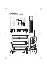
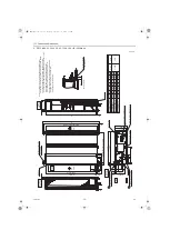
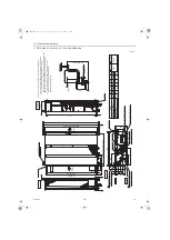
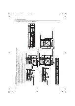
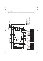
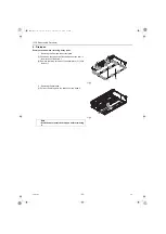
[1] Refrigerant system diagram
(A)
Gas pipe thermistor TH23
(B)
Gas pipe
(C)
Liquid pipe
(D)
Brazed connections
(E)
Strainer (#100 mesh)
(F)
Linear expansion valve
(G)
Liquid pipe thermistor TH22
(H)
Heat exchanger
(I)
Room temperature thermistor TH21
(H)
(I)
(F)
(E)
(E)
(C)
(G)
(A)
(D)
(B)
Capacity
PEFY-
M20, 25, 32, 40, 50VMA(L)(2)-A
PEFY-
M63, 71, 80, 100, 125, 140VMA(L)-A
PEFY-
M63, 71, 80, 100, 125VMA2-A
Gas pipe
ø12.7 [1/2]
ø15.88 [5/8]
Liquid pipe
ø6.35 [1/4]
ø9.52 [3/8]
HWE19070.book Page 22 Thursday, September 12, 2019 3:46 PM

