background image

11

GB

D

F

E

I

NL

GR

RU

TR

CZ

SV

HG

PO

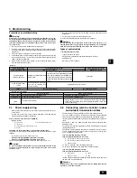
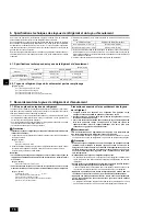
9.1. Power supply wiring

Power supply cords of appliances shall not be lighter than design 245 IEC 57
or 227 IEC 57.

A switch with at least 3 mm [1/8 in] contact separation in each pole shall be
provided by the Air conditioner installation.

Power cable size: more than 1.5 mm

[AWG16]

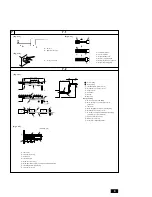
[Fig. 9.1.1] (P.4)

A

Switch 16 A

B

Overcurrent protection 16 A

C

Indoor unit

D

Total operating current be less than 16 A

E

Pull box

[Selecting non-fuse breaker (NF) or earth leakage breaker (NV)]

To select NF or NV instead of a combination of Class B fuse with switch, use the
following:

In the case of Class B fuse rated 15 A or 20 A,

NF model name (MITSUBISHI): NF30-CS (15 A) (20 A)
NV model name (MITSUBISHI): NV30-CA (15 A) (20 A)

Use an earth leakage breaker with a sensitivity of less than 30 mA 0.1 s.

 Caution:

Do not use anything other than the correct capacity breaker and fuse. Using
fuse, wire or copper wire with too large capacity may cause a risk of mal-
function or fire.

2. Remote controller cables

Types of cables

Cable diameter

Length

MA remote controller

Sheathed 2-core cable (unshielded) CVV

0.3 to 1.25 mm

2

 [AGW22 to 16]

Less than 200 m [656 ft]

M-NET remote controller

Sheathed 2-core cable (unshielded) CVV

0.3 to 1.25 mm

2

 [AGW22 to 16]

Add any portion in excess of 10 m [32 ft] to within the longest allowable
transmission cable length 200 m [656 ft] (Shielding portion is more than
1.25 mm

[AWG16])

System configuration

For a single-refrigerant system

For a multi-refrigerant system

Transmission cable length

Less than 120 m [394 ft]

More than 120 m [394 ft]

Regardless of length

Facility example

(for noise judgment)

Types of transmission

cables

Residence or independent store

without noise

VCTF, VCTFK, CVV, CVS, VVR,

VVF, VCT or shielding wire

CVVS or CPEVS

Building, clinic, hospital or communications

station without noise supposedly generated

from inverter equipment, private power gen-

erator, high-frequency medical equipment,

radio-used communications equipment and

so on

All facilities

Shielding wire CVVS or CPEVS

Length

Less than 120 m [394 ft]

Less than 200 m [656 ft]

<Table 1>

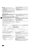
9. Electrical wiring

6. Be sure to connect control cables to the indoor unit, remote controller, and the

outdoor unit.

7. Put the unit to the ground on the outdoor unit side.

8. Select control cables from the conditions given in page 

11

.

 Caution:

Be sure to put the unit to the ground on the outdoor unit side. Do not con-
nect the earth cable to any gas pipe, water pipe, lightening rod, or telephone
earth cable. Incomplete grounding may cause a risk of electric shock.

Types of control cables

1. Wiring transmission cables

Types of transmission cables

Design wiring in accordance with the following table <Table 1>.

Cable diameter

More than 1.25 mm

[AWG16]

Precautions on electrical wiring

 Warning:

Electrical work should be done by qualified electrical engineers in accord-
ance with “Engineering Standards For Electrical Installation” and supplied
installation manuals. Special circuits should also be used. If the power cir-
cuit lacks capacity or has an installation failure, it may cause a risk of elec-
tric shock or fire.

1. Be sure to install an earth leakage breaker to the power.

2. Install the unit to prevent that any of the control circuit cables (remote control-

ler, transmission cables) is brought in direct contact with the power cable out-
side the unit.

3. Ensure that there is no slack on all wire connections.

4. Some cables (power, remote controller, transmission cables) above the ceiling

may be bitten by mouses. Use as many metal pipes as possible to insert the
cables into them for protection.

5. Never connect the power cable to leads for the transmission cables. Other-

wise the cables would be broken.

9.2. Connecting remote controller, indoor

and outdoor transmission cables

Connect indoor unit TB5 and outdoor unit TB3. (Non-polarized 2-wire)

The “S” on indoor unit TB5 is a shielding wire connection. For specifications
about the connecting cables, refer to the outdoor unit installation manual.

Install a remote controller following the manual supplied with the remote con-
troller.

Connect the “1” and “2” on indoor unit TB15 to a MA remote controller. (Non-
polarized 2-wire)

Connect the “M1” and “M2” on indoor unit TB5 to a M-NET remote controller.
(Non-polarized 2-wire)

Connect the remote controller’s transmission cable within 10 m [32 ft] using a
0.75mm

2

 [AWG18] core cable. If the distance is more than 10 m [32 ft], use a

1.25 mm

2

 [AWG16] junction cable.

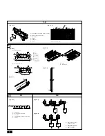
[Fig. 9.2.1]


(P.4) MA Remote controller

[Fig. 9.2.2]


(P.4) M-NET Remote controller

A

Terminal block for indoor transmission cable

B

Terminal block for outdoor transmission cable

C

Remote controller

DC 9 to 13 V between 1 and 2 (MA remote controller)

DC 24 to 30 V between M1 and M2 (M-NET remote controller)

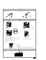
[Fig. 9.2.3]


(P.5) MA Remote controller

[Fig. 9.2.4]


(P.5) M-NET Remote controller

A

Non-polarized

B

TB15

C

Remote Controller

D

TB5

The MA remote controller and the M-NET remote controller cannot be used at
the same time or interchangeably.

 Caution:

Install wiring so that it is not tight and under tension. Wiring under tension
may break, or overheat and burn.

01_KB79P491H01_GB.p65

6/23/09, 4:22 PM

11

Summary of Contents for CITY MULTI PEFY-P06NMAU-E

Page 1: ...ANUAL For safe and correct use please read this installation manual thoroughly before installing the air conditioner unit MANUEL D INSTALLATION Veuillez lire le manuel d installation en entier avant d installer ce climatiseur pour éviter tout accident et vous assurer d une utilisation correcte ...

Page 2: ...7 16 357 14 1 16 122 4 13 16 33 1 5 16 41 1 5 8 217 8 9 16 C A B D A Access door B Electrical parts box C Air inlet D Air outlet E Ceiling surface F Service space viewed from the side G Service space viewed from the direction of arrow 1 600 mm 23 5 8 in or more 2 100 mm 3 15 16 in or more 3 20 mm 13 16 in or more 4 300 mm 11 13 16 in or more Model PEFY P06 08 12NMAU E PEFY P15 18NMAU E PEFY P24 27...

Page 3: ...it as large as possible About 10 cm 3 15 16 in F Indoor unit G Make the piping size large for grouped piping H Downward slope 1 100 or more I O D ø38 1 1 2 in PVC TUBE for grouped piping 9 mm 3 8 in or more insulation J Up to 550 mm 21 11 16 in N Drain hose accessory O Horizontal or slightly upgradient 7 2 Fig 7 2 2 C B A L D D D E K M B H I Max 20m 65ft 1 5 2m 5 7ft G F F F B C D D G F E H A 32 1...

Page 4: ... B Terminal block for outdoor transmission cable C Remote controller 9 2 Fig 7 3 1 7 3 A Insert pump s end 2 to 4 cm 13 16 to 1 5 8 in B Remove the water supply port C About 2500 cc D Water E Filling port F Screw Fig 8 0 2 SWE Fig 7 3 2 Fig 8 0 3 Fig 8 0 4 Indoor controller board A B F C D E A B G F A A B C D E F G C E Duct Air inlet Access door Canvas duct Ceiling surface Air outlet Leave distanc...

Page 5: ...ound terminal C Shield wire D The earth wire from two cables are connected together to the S terminal Dead end connection E Insulation tape To keep the earth wire of the shielded cable from coming in contact with the transmis sion terminal 9 3 Fig 9 3 3 Fig 9 3 4 Fig 9 3 5 C Terminal box D Knockout hole E Remove A Screw holding cover 1pc B Cover Fig 9 3 1 Fig 9 3 2 A Non polarized B TB15 C Remote ...

Page 6: ...ins Improper handling may result in injury When handling this product always wear protective equipment EG Gloves full arm protection namely boiler suit and safety glasses Improper handling may result in injury If refrigerant gas leaks during installation work ventilate the room If the refrigerant gas comes into contact with a flame poisonous gases will be released Install the air conditioner accor...

Page 7: ...t on a structure that may cause leakage When the room humidity exceeds 80 or when the drain pipe is clogged condensation may drip from the indoor unit Perform collective drainage work together with the outdoor unit as required The indoor models should be installed the ceiling over than 2 5 m from floor 1 4 Before getting installed moved elec trical work Caution Ground the unit Do not connect the g...

Page 8: ...1 2 P 2 C Nuts field supply D Washers field supply E M10 hanging bolt field supply 5 2 Confirming the unit s position and fix ing hanging bolts Use the gage supplied with the panel to confirm that the unit body and hanging bolts are positioned in place If they are not positioned in place it may result in dew drops due to wind leak Be sure to check the positional relationship Use a level to check t...

Page 9: ... is designed to operate in a system that the refrigerant pipe from an outdoor unit is received by BC controller and branches at the BC controller to connect between indoor units For constraints on pipe length and allowable difference of elevation refer to the outdoor unit manual The method of pipe connection is brazing connection Caution Install the refrigerant piping for the indoor unit in accord...

Page 10: ...e and outlet duct to prevent condensa tion Be sure to change the position of air filter to the position where it can be serv iced Fig 8 0 1 P 4 A In case of rear inlet B In case of bottom inlet A Duct B Air inlet C Access door D Canvas duct E Ceiling surface F Air outlet G Leave distance enough to prevent short cycle Procedure for changing the rear inlet to the bottom inlet Fig 8 0 2 P 4 A Filter ...

Page 11: ...pe water pipe lightening rod or telephone earth cable Incomplete grounding may cause a risk of electric shock Types of control cables 1 Wiring transmission cables Types of transmission cables Design wiring in accordance with the following table Table 1 Cable diameter More than 1 25 mm2 AWG16 Precautions on electrical wiring Warning Electrical work should be done by qualified electrical engineers i...

Page 12: ... box cover with that shown on the rating name plate 1 Remove the screw 1pc holding the cover to dismount the cover Fig 9 3 1 P 5 A Screw holding cover 1pc B Cover 2 Open knockout holes Recommend to use a screwdriver or the like for this work Fig 9 3 2 P 5 C Terminal box D Knockout hole E Remove 3 Fix power source wiring to terminal box by using buffer bushing for tensile force PG connection or the...

Page 13: ... de protection pour manipuler ce produit Par ex gants protection intégrale des bras par combinaison et lunettes de sécurité Vous risqueriez de vous blesser En cas de fuite de gaz durant l installation aérez la pièce Si le gaz réfrigérant entre en contact avec une flamme il y aura émission de gaz toxiques Installez le climatiseur en respectant les instructions du manuel d installa tion En cas d ins...

Page 14: ...èles intérieurs doivent être installés à un plafond situé à plus de 2 5 m du sol 1 4 Avant de procéder à l installation déplacement installation électrique Précaution Mettez l appareil à la terre NNe branchez pas le fil de mise à la terre à un tuyau de gaz ou d eau un para tonnerre ou câble téléphonique de terre Une mauvaise mise à la terre peut pro voquer des risques d électrocution Installez le ...

Page 15: ... 1 Fixation des boulons de suspension Fig 4 1 1 P 2 Fournir une structure résistante à l endroit de suspension de l appareil Cadre de suspension Plafond La structure du plafond varie d un édifice à un autre Pour plus d informa tions veuillez prendre contact avec la société de construction de l immeuble Si nécessaire renforcez les boulons de suspension avec des supports antisismi ques comme mesure ...

Page 16: ... tuyaux de réfrigérant Toujours utiliser des soudures non oxydantes afin qu aucun corps étranger ni aucune humidité ne pénètre à l intérieur du tuyau Revêtir le siège du goujon d huile pour machine réfrigérante et le serrer fermement à l aide de deux clés Placer une entretoise métallique pour soutenir les tuyaux de réfrigérant de telle sorte qu aucune charge ne s applique à la sortie des tuyaux de...

Page 17: ...s de fonctionner sans télécommande Veiller au bon écou lement en utilisant un tube transparent 4 Après confirmation annuler le mode d essai et couper l alimentation principale Si le connecteur est relié au côté ON de SWE le débrancher et le rebrancher au côté OFF puis fixer capot du port d alimentation en eau dans sa position initiale Fig 7 3 1 P 4 Fig 7 3 2 P 4 8 Raccords des conduites Lors du ra...

Page 18: ... Ne pas raccorder le câble de terre à une conduite de gaz à une conduite d eau à un paratonnerre ou à un câble de terre téléphonique Une mauvaise mise à la terre peut consti tuer un danger d électrocution Types de câbles de commandes 1 Mise en place des câbles de transmission Types de câbles de transmission Concevoir le câblage conformément aux indications reprises dans le tableau sui vant Table1 ...

Page 19: ...sance électrique entre les éléments accessibles et le circuit de con trôle doit être de 2 750 V minimum 9 5 Sélection de la pression statique extérieure Le réglage d usine admet une pression statique extérieure de 0 20 in WG 50 Pa par conséquent aucun commutateur n est nécessaire pour une utilisation en deçà des conditions standard Fig 9 5 1 P 5 9 6 Configuration des adresses Toujours effectuer ce...

Page 20: ...ress telephone number on this manual before handing it to the customer This product is designed and intended for use in the residential commercial and light industrial environment HEAD OFFICE TOKYO BLDG 2 7 3 MARUNOUCHI CHIYODA KU TOKYO 100 8310 JAPAN ...

Reviews: